I had been using a piece of wood to prop my doors open, but while at Allan’s I noticed that he would slide an undersized bolt into a hole in the hinge to keep the doors open. This keeps the door opening clear and prevents the door from becoming a guillotine when you accidentally bump the wood. I’m not sure what the purpose of the hole is, but it’s not used when using door actuators. I bought two 1/4” diameter x 5” long quick-release pins from McMaster. There’s no need for anything other than round piece of metal, but I wanted to attach a lanyard (a piece of string) to keep it from getting misplaced. The pin only needs to be long enough to bridge the bolts, but I found that the extra length makes things a bit easier.
Snow Forecast and Axles
I had left my trailer at Allan’s while he was working on the car, but, as you can see in the snow forecast above, we’re expecting an epic Nor-easter which would have buried and frozen it in place. So, I hauled the car back yesterday. I’m glad that I’m in a state that’s lower on the f’d scale.
A few months ago I ordered custom axles. I wasn’t sure how to accurately measure them, but after trying several approaches I wound up using a welding rod. I kept snipping small pieces off of the end with a diagonal cutting plier until it fit snugly and then I measured the rod on the bench. Both sides were within 1/32” of the same length.
While 930 CV joints will accommodate fairly steep angles it’s best to keep the angle as shallow as possible at ride height. This is particularly true for high-torque drivetrains. As can be seen in the pictures below the axles have a minimal angle when compared to a Ricardo or a Graziano when mounted in a SL-C.
Door Cards
After a little tweaking with a sander and Dremel grinding wheel, we mounted the door cards to the doors with 10-32 nutserts. The right door card fit well, but the left one needed to be modified. The top rear corner had a 5/8” gap from the door. After determining where the door card started to pull away from the door, we cut it into two pieces. Both pieces were sanded on the front and back to prepare them to be epoxied. Clear packing tape was placed under the cut line to prevent the epoxy from sticking to the door, the small piece was held in place with a temporary screw, and epoxy was mixed with mirco balloons to a peanut-butter consistency. The mixture was pressed into the cut line with a wood tongue depressor and after it kicked the door card was removed, the seam was sanded smooth and fiberglass cloth was added to the backside. Problem solved.
The next step is to validate that door cards clear the removeable side impact bars.
When Pigs Fly
I decided to make some significant mods to my “finished” fuel tank. Unfortunately, I had gone overboard covering it with Second Skin Damplifier Pro. Holy shit is that stuff is a nightmare to remove. Their guarantee to “stick until pigs fly” is pretty close to true. As their marketing states the butyl layer is “elastic with a high tensile strength and elongation” which makes it difficult to tear pieces off. It sticks to whatever you stuck it to and once the foil constraint layer has been removed, it sticks to everything it touches (tools, workbench, floor, itself, gloves, fingers, whatever). It grudgingly comes off in small goopy pieces and leaves behind smaller pieces that need to be scrubbed off with acetone and a Scotch-Brite pad.
While lamenting this situation Hill mentioned that he uses bags of dry ice to remove sound deadener. Damplifier Pro is rated to -75 °F and dry ice is -109.8 °F, so I decided to give it a try. My local ice distributor sells it in blocks, slices, pellets and high-density pellets. Since all of the surfaces on the fuel tanks are flat, I decided to go with slices because they would maximize the contact area. I laid a slice of dry ice on the tank and covered it with several shop rags to reduce the rate of sublimation. After a several minutes elapsed, I used a paint scraper to pry up the material. It was less sticky, easier to remove and there was less material left on the tank, but it was still a lot of work.
I then experimented with the duration of exposure to the dry ice which make a big difference. For example, I left a slice in one spot during lunch. With that long of a duration I found it difficult to pry the material up and as I pried it would begin to bend and then crack off… that’s what I call frozen. While it wasn’t nearly as easy to remove as I wanted no material was left on the tank.
When I achieved optimal duration, the slice would freeze to the material requiring a gentle pry with the paint scraper to remove. The containment foil just popped off. Using the paint scraper, I pried up a corner of the butyl far enough to grab it with my hands. I was then able to peel everything in one piece with my bare hands without leaving anything stuck to the tank. The material felt like normal rubber and wasn’t in the least sticky, at least until it warmed up.
In the picture below I had just placed a slice and two broken pieces of dry ice are on top of a large piece of Damplifer Pro. I had previously removed the containment foil (an unnecessary step) which makes it looks wet, but it’s completely dry. I pulled up the half covered by the slice, repeated the process on the other half and it came off in one piece. I’m not sure what the temperature was, but frost would develop on the bare aluminum around the material.
The dry ice allows easy removal without the need for flying swine. Vertical or curved surfaces would be more difficult because you would need to use pellets in a bag resulting in less contact with the dry ice. It takes patience to get the material to the optimal temperature so I would position and cover the slice, do something else, remove the chilled section and repeat.
I think I used less than three slices to do the entire tank. What to do with the leftover dry ice? A smoking blue martini of course (my photo didn’t show the smoke as well as this one). My dog fears the animated drink as much as the vacuum cleaner, but she came over to check it out once as soon as it stopped bubbling.
Doors Blended with Modified Front Wheel Outlets
I modified the front wheel well outlets which required me to cut the stock body line on the doors which are several inches below the nose parting line (i.e., the line that separates the nose and body).
The holes in the doors have been patched and a clean body line has been created and blended into the doors.
When Allan first picked up one of the doors he said, “you got a bad doors.” He knew by the weight that the fiberglass was much thinner than it should be. To demonstrate, he turned off the lights and shone a flashlight on the gelcoat side. Large sections of the door weren’t much more than gelcoat. It’s understandable that there might be some thin spots, but both doors were shoddy and the nose and tail have similar issues. This really pisses me off. It would have taken the fiberglass terrorist with the chop gun what, two extra minutes? In addition, the fiberglass on the nose, center section and tail wasn’t rolled out. Whomever glued the interior shell should have noticed how thin the door was and they could have easily laminated a few layers of chopped mat. But no, they just bonded them together and shipped it.
Fixing this after the fact is several orders of magnitude more work than to do it right the first place because there is only a small opening in the interior shell to access the backside of the door. Not as bad as building a ship in a bottle, but you get the point. You have reach through the opening and apply dewaxer, abrade with 40-grit sandpaper and then apply multiple layers of cloth. The good news is that Allan has had to do this before and this is one of the first things that he checks when he gets a SL-C. Apparently the quality of the SL-C bodies have gotten much worst over time so it’s critical that you check your fiberglass before doing any bodywork. Put the pieces on sawhorses, turn off the lights and have someone slowly move a flashlight across the gelcoat.
As you can see in the picture above, Allan also has a GT-R in the shop and I compared the quality of the fiberglass. The GT-R fiberglass was really nice and made my SL-C body look shoddy. That said, I prefer the SL-C. This isn’t about the molds. The subcontractor who makes the GT-R bodies does a high-quality job whereas the one who makes the SL-C bodies doesn’t. The issues are fixable, but it’s not something that a builder should need to do. The fiberglass parts are incongruous with the quality found in the rest of the parts.
Front Wheel Outlet
Over two years ago I posted about modifications that I was going to make to the side of car.
I decided to go with Option A3, which requires the most work. I focused on the area behind the front wheel (i.e., the section circled in red). Option A1 is stock in this area so comparing it to A3 illustrates what changes need to be made. I purchased a pair of QL-38 Quick-Latches and made several point-of-no-return cuts to the doors and spider, but I got busy with other parts of the car.
Last week I worked with Allan to finalize the mod. The two pictures below show where the initial cuts were expanded.
We were able to cut the wheel well higher than what we initially thought. This not only looks better, but it will enable more air to flow from behind the tire. We also took the opportunity to fill in the “beer holder” and the curved vertical piece behind the wheel. Everything still needs to be fine tuned, but the heavy lifting on this part of the mod is done. Note that the pictures depict the Quick-Latch ball stud inserted into the latch. It will eventually be installed in the nose flange.
The Quick-Latch has several advantages over the AeroCatch;
Significantly smaller
Significantly easier to install (one cut with a hole saw vs. a large awkward shape and five holes)
All metal
Ball stud is stainless steel
Rated to 500 pounds each
Allan plans to recommend upgrading the AeroCatches to Quick-Latches on his future builds.
The next step is to mount the ball studs to the nose flange, blend the cuts in the doors to match the new body line and fabricate covers for the door hinge cutouts.
Nose Hinges Mounted
I finally got around to mounting the nose hinges that Bob and I created. The foot of each hinge is bolted to a splitter support link which connects to the nose frame. The nose frame is robust (120-wall 1” OD 4130) and I have used it as a jacking point and noticed no deflection, so the front of the splitter is absolutely rock stable.
To achieve clean esthetics, I used a clevis with a pressed pin to retain the rod end that connects to the hinge’s foot. This results in no bolt head or nyloc. On the other end I used a teardrop-shaped stainless-steel clevis to capture the tab on the nose frame. The tab is just tack welded for now… and, yes, I should have primed the nose frame to keep the surface rust down, but that will be addressed when I have it Cerakoted.
The fiberglass where the hinge mounts on the driver’s side OK, but it was paper thin on the passenger's side. Allan reinforced both sides by creating fillets in the joints with microfiber filler mixed with epoxy and then applying 10 layers of 10-ounce cloth. Care was taken to ensure that the load on the small areas where the hinges mount were as distributed as possible. Anyone installing a hinge like this should carefully reinforce this area.
The 10" tall wheel cribs from Race Ramps put the car at a perfect height for working on it. The car is too low to comfortably do body work on the floor and if you use a lift or jack stands the suspension is unloaded which, according to Allan, slightly changes gaps etc. So, he does all gaps and most body work on the wheel cribs. The Race Ramp ones are very light, so they are easy to toss on top of a cabinet when not in use.
The next steps are:
Install the air springs. This will require some thought and effort because I significantly cut back the vertical fiberglass pieces that are bonded to the underside of the nose to clear the nose frame. This is where the air springs attach.
Fabricate and install the rear splitter support links. This will require some thought to clear the intercoolers and the front wheel well liner.
Door Actuators & Emergency Release
I hauled my car down to Allen’s and we installed the door actuators and brackets discussed in a previous post. The electric door actuators have several advantages. Besides the cool factor, they apply tension to the door ensuring that it’s firmly seated on the door seals, they keep the door from rattling, they remove the need for a door handle resulting in a clean exterior and they provide a locking mechanism.
However, if there’s a failure they could potentially lock you into or out of your car. One builder had an electrical failure while driving on the highway. He was stuck on the shoulder, baking in the summer sun with the door locked shut. Fortunately, he had his phone and the foresight to build an external harness with a portable battery to power the door open (although his use case was him locked out rather than in.) He called his wife and by the time she arrived to free him he was cooked medium rare.
While that story ended well, a Texas man and his dog died in the parking lot of a waffle house after becoming trapped in a 2007 Corvette. Apparently, an electrical system failure prevented the electric locks and horn from working. Unbeknownst to the owner, there is a manual release lever between the driver’s seat and the door (article here). IMO it’s extremely important to have an emergency release.
I have seen multiple pictures of SL-C’s with pull-pin-based door releases for the actuators, but to my knowledge none of them work. The issue is that the actuator applies about ??? pounds of tension when the door is closed. The good news is that Peter, who built the first SL-C with electric doors, has been working with a mechanical engineer to develop a reliable release mechanism. As can be seen in the video below, Allan and I tested it. It is well engineered and it worked great.
Note that the cutouts in the door and spider are related to my body mods and have nothing to do with the actuators and release mechanism. That said, having installed many doors and actuators, Allan was interested to see what happens inside the door. in addition, I measured the tension to be about 90 pounds and not the 160 pounds that I mentioned in video.
I’m talking with Peter about a couple of enhancements and a potential group buy.
My plan is to mount a red T-handle with a “DOOR RELEASE” label on it to the side of the footwell immediately forward of the door. It will look race and no way is someone going to miss it. I will also run a wire from each door into the nose so that I can open the doors if I get locked out. I don’t see that as a security risk because a would-be thief would need to know where the wires were and have a pair of pliers. In addition, my steering wheel is removeable and they would need a Krontec quick disconnect and know what my proprietary CAN bus message is to start the car.
Supra Tail Light Change
I had figured out how to mount the C7 tail lights and Kevin had sorted out how to fit them into the body. So it’s time to just do it, right? Nope… Brian mentioned the 2020-2021 Toyota Supra tail lights which weren’t out when I settled on the C7 lights. They are more modern, exotic and make the C7 lights look cheap.
The outer top corner has a big radius which isn’t even close to fitting the body. I’ll need to recontour the top corner of the body from the middle of the rear wheel well to the edge of the tail light. There is also a pretty big front-to-back curve which is OK because I’m going to stretch the back of the car 5-6” to make room for the mufflers and a proper diffuser. It will be a lot of work, but worth it in the end.
I couldn’t find a wiring diagram or harness part number online so I went to a Toyota dealer. The parts guy couldn’t figure it out either and he asked the techs. To determine the part number for the harness they need a VIN. To get a wiring diagram the car must be connected to their computers! WTF happened to the Right-to-Repair Bill?
It doesn’t look like I’m going to be able to get a sub harness, a pigtail or figure out what the connector is so I’m going to solder wires to the pins and fill the socket with potting epoxy. The first step was to figure out the wiring without letting the smoke out:
Big Pin: Ground
Small Top Pin: Brake/Turn Light (12V)
Small Middle Pin: Running Lights (12V)
Small Bottom Pin: Doesn’t appear to do anything, it might be diagnostic related.
The lights look great when lit as seen in the video below.
Kevin did some initial sketches. I need to figure out which direction I want to go…
X-Pipe
I’m going to run an x-pipe under the transaxle. Since I’m primarily interested in smoothing and reducing the magnitude of the exhaust, as opposed to maximizing HP, I went for what would fit best. The x-pipe is composed of pie cuts sourced from 3.5” OD 0.047” wall Grade 1 titanium tube. They were cut at a 9.5-degree angle on a horizontal bandsaw using the tube clamp that I designed and 3D printed in a previous post. The edges were touched up on a belt sander, the inside edges were where deburred and the exterior face was brushed with a tube sander running a conditioning belt.
The pie cuts were tacked into curved symmetrical left and right pipes. A scrap straight section (not pictured above) was tacked to both ends of each pipe to prevent the end pie cuts from deforming during welding. After welding, the two pipes were scalloped on the bandsaw and tack welded to form an “X.” They won’t be permanently welded together until the rest of the exhaust is in place. That’s a total of 22 pie cuts and 20 welds spanning 78” just for the two pipes!
Abe's a pro so he was able to achieve the relatively low alpha case without any special equipment. When welding titanium he takes extra care to ensure that the bead is completely shielded by the cup until it cools. While he's used a parts-per-million (PPM) oxygen analyzer at other job to insure a proper shield, he doesn't have one in his shop. Instead he just runs more argon than he normally would. To ensure that the hot bead is always under the cup he closes the doors to prevent an errant breeze, he's careful with torch angle and he only does 10-12 dabs before stopping. At which point he flips his helmet up while keeping the cup over the bead with the gas running for another 15-20 seconds after which he rotates the tube and repeats the process. Given his experience level and that this isn't an aerospace part, he doesn't use a thermometer to determine when the bead is cooled. An excess of argon wastes a little gas and takes a few more seconds per cycle. Too little and you get alpha case.
I decided to try heat coloring the scraps from the scallop cuts with a MAP torch. Titanium goes from yellow, to purple, to dark blue to light blue as it’s heated. I cleaned the one on the left with acetone. For the right one, I removed all of the weld oxidation with a surface conditioning before cleaning it with acetone. It looks significantly more blue in person. I’m going to experiment some more. That said, I’m not sure that the cool colors that can be achieved will remain after the car has been run hard a couple of times.
Engine Oil Inlet Fitting
In a previous post I replaced the oil inlet fitting that came with the Daily Engineering dry sump pan with one from Kurt Urbane. I went from colliding with the merge collector to having about 1/4” of clearance. Do’h! That’s too close.
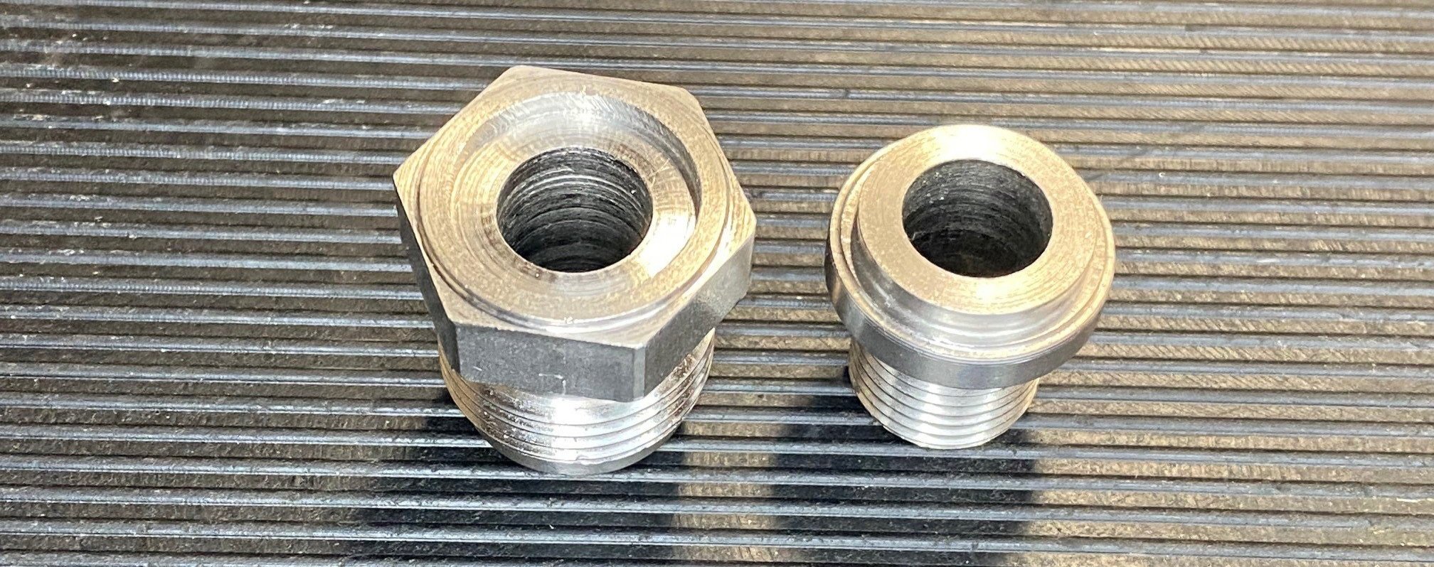
The only solution was to shorten one of them on the lathe. The Kurt Urbane was a better starting point because the hex diameter (i.e., what you wrench on) was smaller, 0.932” rather than 1”, which provides better block clearance, and it has more threads into the block which means that it’s less likely to leak. That said the hex was taller so the first step was to turn it down from 0.366” to 0.311.” I then used a cutoff/parting tool to split the part into two pieces.
I wanted the two pieces to interlock to ensure that concentricity was maintained during welding. Machining the male side was easy to figure out, but I was confused about the female side — some things never change LOL. I’ve done basic boring operations before, but I wasn’t confident that I could achieve the tolerance that I wanted with a perfectly square inside corner. I then figured out that I could load an end mill in the tailstock and do a simple plunge cut. After some consideration I ordered an 11/16” center cutting, 4-flute, square end mill. What I didn’t think about was that its shaft size was 5/8.” The R8 collets for my mill go up to 7/8,” but the Jacob’s chuck in the lathe’s tailstock only goes to 1/2”. So I returned the end mill and purchased one with a 1/2” shank. Despite that setback the second end mill worked great and I got to use the tailstock’s DRO for the first time.
The male side involved a simple turning operation, but setting it up wasn’t as easy as I thought it would be. I could only put 0.1” in the chuck and I couldn’t get the part concentric within the jaw. After some research I figured out that I could put a live center in the tail stock and then push the part onto the live center using a long rod through the backside of the spindle. It would have been nice to leave the live center in place, but there was it was in the way of the cross slide so it had to be removed. I was able to get the part concentric, but after taking a bit of material off I realized that there was too little material for the chuck to grab.
Since the part was made of stainless steel, I lightly grabbed the threads with the chuck and only turned 0.005” (0.010” total) per pass. That worked well and there was no damage to the threads.
The parts were fixtured by running a bolt through the center with two washers and a hex nut. Since the parts were self indexing there was no need to worry about alignment. The parts where then TIG welded.
I’m going to have to pull the engine and remove the headers to see if it all works. I think that I might need to modify a socket to clear the block and perhaps grind the block a bit. Time will tell.
Chopping the Tail
As I’ve previously mentioned, I’m completely changing the rear 20% of the tail. The stock tail is a single pivoting piece that supports the tail lights and has an integrated “diffuser.” This approach is easy to implement, but the pivot motion interferes with the wing and exhaust and the molded diffuser is more of a parachute that anything else. Mine will have a fixed rear bumper that supports the wing, tail lights and a functional diffuser. The engine cover will hinge backwards towards the tail.
About 18 months ago I chopped the tail. Before taking a reciprocating saw to it, I spent some time thinking about how I would maintain the correct orientation once the hinge points were cut off. I welded a temporary support to the top of the rear suspension brace. It has two locating pins (borrowed from the nose) that stick through the tail to index and support it in the middle. From the underside I drilled a hole through the temporary bracket and the fiberglass - this got the X/Y coordinates perfect. I then tapped the bracket, enlarged the hole in the fiberglass and screwed the indexing pins in. By threading the indexing pins up and down I was able to get the Z axis perfect. I then added a jam nut so that it wouldn't move.
While the indexing pins locate the tail they won’t prevent it from deforming when the duck tail is removed due to a combination of the weight of the wheel arches and tension in the fiberglass which is released when the duck tail is removed. To address this, I tapped holes in the tube and installed leveling feet upside down. Since they have a ball socket I was able to get the wheel arches perfectly dialed in. I was careful about how I cut the tail so that I can use the removed piece to validate that everything is where it's supposed to be. As can be seen in the video above, the tail doesn’t deflect when the chopped section is removed.
With the tail chopped, indexed and supported, I needed to stiffen the engine cover and provide a way to mount the hinges. While the final version will achieve this via carbon fiber tubes and bonded steel plates, I have a lot to figure out before then. So, I welded some right-angle to a 3/4" square steel tube and bolted it to the back edge of the engine cover.
I’ve also started finalizing the tail subframe which is made of 1” OD 0.120” wall 4130 tube. It supports the wing, transaxle oil cooler, rear bumper, tail lights, titanium exhaust, and engine cover.
Rather than design and fabricate a hinge I looked for an aftermarket billet one. The majority that I found are for 60s and 70s muscle cars and I settled on 60’s era Mustang trunk hinge. I didn’t want to splurge on the billet version until I had proved things out, so I bought a stamped steel one on eBay. I’m glad that I did because I had to hack their mounting plates to get them to fit around the temporary tube bolted to the back of the engine cover. The hinges have vertical slots to facilitate adjustment so I fabricated some temporary plates with horizontal slots. I didn’t want to tack weld them to the tail subframe so I purchased several clamping two-piece shaft collars with a 1” ID and welded the plates to them. This provides a lot of adjustability and is easy to remove when I fabricate the final version.
I took the same shaft collar and slotted bracket approach to temporarily mount the wing. Once the hinge was mounted I removed the locating the pins and opened the engine cover. It was as smooth as I hoped, but it’s a two-person job because the engine cover has a lot of flex. Once I stiffen it and add air springs it will hopefully be a one-handed, OEM-like exercise.
I need to make a big decision on which tail light I’m going to use so that I can begin to finalize the body mods, exhaust and diffuser.
Cat-Back Exhaust: Part 1
I started fabricating the cat-back exhaust system. The plan is to fabricate stainless steel sections for the catalytic converters (cats) that connect to the merge collectors and titanium mufflers via v-bands. My engine builder recommended an Air-Fuel Ratio (AFR) of 10.5-11 which is crazy rich and will quickly burn out any cat. I’m going to try running cats with a leaner AFR. To provide the best chance of success, I purchased G-Sport catalytic converters which are EPA compliant and support up to 850 HP each. Worst case, I’ll have to replace these sections with resonators. Time will tell.
I purchased 321 stainless steel transition cones from SPD to adapt the 3” merge collector outlets to the 4-1/2” cat ODs. I used a hydraulic press, a die, and 3-1/2” 321 stainless steel tube to fabricate transitions from 4-1/2” cat OD to the 3-1/2” down stream exhaust. Abe welded the transitions and tacked an elbow section and a flange.
Mr. Miyagi would have found automotive fabrication great training — you know the whole Wax On, Wax Off thing. Parts come on and of the car many times and it makes sense to find ways to make that process easier. For example, I swapped all of the suspension nylocs with plain nuts for the build phase. Abe modified a Vice Grip to have v-band jaws as shown in the picture above. The cats have already been in-and-out a dozen times (times two because there are two sides) and it’s already saved a lot of time and we’re no where near done.
I’m going to install cutouts before the cats and I purchased several to figure out which would work best. I selected 2.5” cutouts from DPW. Although the exhaust is 3.5” there is no need to have the cutouts be that large because the exhaust will take the path of least resistance. The worst case is that some exhaust flows through mufflers and the car isn’t quite as loud. DPW provides an inlet tube and a turn-down tube, neither of which worked for my situation. No problem, I’ll make my own. The challenge was that DPW uses proprietary v-band flanges. They’re very lightweight which makes sense because they only need to support a fraction of the weight of a standard v-band. I tried for a couple of weeks to determine if they could provide standalone flanges to no avail. That left me with two options: salvage them or fabricate new ones from scratch.
I went for option one which is a lot less work and requires no additional material. The first step was to cut the flanges from the tube with an abrasive cutoff wheel. Once that was done I chucked the flange in the lathe by grabbing the v-band (as opposed to the tube). Machining relatively thin-walled tube on the lathe is always a little nerve racking so I took a bunch of shallow passes with a boring bar. The flange from the turn-down tube was trickier than the one from inlet tube because the curvature of its tube projected inside the flange. This resulted in a 50% interrupted cut (i.e. cut for 180 degrees and then skip for 180 degrees ). While the sounds made me wince, everything worked fine.
I only purchased one cutout to ensure that everything worked. I need to purchase a second one and repeat the process twice.
Rear Sway Bar Links & Bellcrank Brackets
I mounted the rear sway bar in a previous post and the next step was to attach it to the bellcranks. The adjustable sway bar blade accepts a 3/8” rod end. However, the other side of rear sway bar link is attached to the same 1/2” bolt that affixes the shock absorber to the bellcrank. While it would be easy to fabricate a link with a 3/8” rod end on one side and a 1/2” rod end on the other side, that would be overkill. 1/8” might not seem like a big difference, but a 1/2” rod end dwarfs a 3/8” one.
It also requires a larger tube-end weld nut, jam nut and tube which adds weight and bulk making it more difficult to clear the shock absorber spring. I spent a couple of nights scouring the Internet for a unicorn — a rod end with a 1/2” bore and a 3/8” male thread. If it exists, I couldn’t find it.
I considered machining a 3/8” shoulder and a 3/8” thread on the tip of a 1/2” Grade 8 screw, but I’m not comfortable machining threads yet. I then realized that a shoulder screw would be a better starting point. They are comparable in strength to a Grade 8 screw and McMaster offers 1/2” shoulder screws with a 3/8”-16 thread with grip lengths in 1/4” increments. I purchased two with a 4” grip which was long enough to allow the link to clear the shock absorber. All I needed to do was turn 1/8” off of the last 1” of the grip in the lathe.
That should be easy, right? Nope! No matter what I tried I couldn’t get a good finish. I had purchased an indexable carbide tool set because I didn’t want to learn how to grind High-Speed Steel (HSS) tools. Apparently, carbide likes much higher speed and feed rates than my lathe can do (think CNC). It worked fine on aluminum, but it wasn’t working on this grade of steel. After doing a little research, I discovered Arthur R. Warner Co. who offers indexable HSS inserts. I purchased one of their tool sets and they provided an excellent finish.
Shoulder screws are more difficult than normal screws to install through suspension parts because the shoulder has a 90-degree edge that gets hung up on anything that isn’t perfectly aligned (e.g., safety washers, rod end’s mono ball, etc.). To mitigate this issue I chamfered the 90-degree edge.
The next step was to design and fabricate a bracket to position the link 1.3”from the bellcrank and to put the shoulder screw in double shear.
I laser cut a plate from 1/8” 4130 that attaches to the underside of the bellcrank via the existing 1/2” bolt holes. Using the lathe, I machined a spacer to fit between the bellcrank and the misalignment washer. It’s critical that the misalignment washer binds on the bellcrank (via the spacer) and not the face of the shoulder screw. I used 1”4130 rod to match the OD of the misalignment washer and drilled a 1/2” through hole. To reduce the weight of the piece I machined the all but the last 0.4” of the ID to 3/4”. The lathe would have been ideal for this, but my Jacob’s chuck maxes out at 1/2”.
Instead, I mounted a three-jaw chuck to the mill and used a 3/4” 4-flute end mill. Given the hard alloy steel and cheap end mill I was worried about chatter, but using the online speed/feed calculator (460 RPM) and the quill (as opposed to the z-axis handle) allowed me to cut it like butter. I assume that this was due to the 1/2” hole already being drilled. I had to stop the mill several times to remove the swarf which is as sharp as shit… yeah, I managed to cut my finger which wasn’t a big deal because the mill was off. I had become comfortable dealing with aluminum and this was one of those important lessons which could have been much worst. After employing a Band-Aide, I used a 3/4” countersink to chamfer the spacer’s internal face to make it easier to feed the shoulder screw through it.
I machined a post to support the double shear plate from 3/4” 4130 rod. One end was drilled and tapped for 3/8”-16 and, similar to the spacer, the other end was machined with a 1/2” end mill to reduce weight.
Because all of the welding was going to be done at one end, I fabricated a simple welding jig from consisting of a plate and two spacers. I used aluminum because it’s an excellent heat sink. ER70S rod to add some large tacks that were structurally strong enough, but minimized the chances of warping. I wanted the full circumference welded so he used silicon bronze rod because we didn’t need the strength and it requires half as much current which equates to a lot less heat.
The links were fabricated from 4130 tube, 4130 tube-end weld nuts and stainless steel hex nuts. The aluminum tubes located between the sway bar link and chassis are for the front and right-rear air jacks.
The next step is to run the control cable.
Clutch Installed
I finally got around to installing the triple-carbon clutch that I discussed in a previous post. The first step was to install the pilot bearing in the crankshaft. I applied a little anti-seize on the sides and used a 32 mm socket, a short socket extension and a hammer to tap it into the crankshaft. Easy peasy.
To remove any burrs or imperfections from both the clutch hub and the input spline I applied the provided lapping compound to the input spline and I individually slid each of the three disks back and forth on the spline. This was easy to do, but it was a pain in the ass to remove all of the lapping compound from the spline’s valleys. With that done, it was straight forward to align the clutch and mount it to the flywheel.
Agile Automotive and RPS collaborated to create a complete solution. They provided a larger throwout bearing and a custom spacer to set the correct distance between the throwout bearing and the pressure plate fingers. I used a bearing separator to remove the stock bearing and a hydraulic press to mount the spacer to the new bearing. While using a hydraulic press to push the bearing/spacer assembly onto the slave cylinder I damaged the slave cylinder’s piston. DO’H!
Fortunately Weddle stocks just the piston so I had them FedEx me one. When it arrived I noticed that it was longer than the one that I had, so they FedEx’d a second one and it had the same problem. After some measuring and a lot of discussion, we determined that Albins had installed the wrong piston at the factory! The total height of the piston should be 49.5 mm rather than 58 mm.
The extra length results in a longer shoulder which was a contributing factor to the damage inflicted on the original piston. Had I not damaged it the extra length would have gone unnoticed because there are no part numbers on the pistons and no measurements are provided in the manual. The longer piston would have likely destroyed the $5,000 clutch, requiring me to pull the whole tail of the car apart to replace it!
Once that cluster was sorted out it was an easy matter to reinstall the slave cylinder. I had used a long hex bit socket to remove it, but the wider throwout bearing necessitates a ball end version. The clutch inlet and bleed fittings have tapered threads. The manual didn’t specify a compound so I used Gasolia liquid thread sealant.
The spline isn’t tapered at the tip which makes it more challenging to align it with the clutch hub and you need to be careful to not crack the carbon disks. As can be seen below, the engine was bolted to a hydraulic lift table and a motorcycle scissor jack was placed under the billet oil pan. The transaxle was suspended from an engine hoist via an engine load leveler. This allowed me to get everything lined up without any help and without needing to shake the hell out of the transaxle.
While I was waiting for the parts to arrive, I noticed that one of the socket head cap screws had developed some surface rust — gasp. The studs and 12-point nuts have a nice coating, but all of the socket head cap screws are black oxide. Albins, you couldn’t spring for a extra couple of dollars? So I replaced all 62 socket head cap screws with zinc-plated screws which was irritating because I needed to buy six different types of screws each with a 50 or 100-count box.
Flywheel Installed
I installed the flywheel today. I have an LS7 so I ordered an LS flywheel locating dowel and when I went to install it I realized that it was way too small. WTF? I have a built motor and it has a Callies DragonSlayer billet crankshaft with an LT, rather than an LS, bolt pattern. D’OH! Fortunately, I had ordered the flywheel with the correct pattern.
The LT is clearly designed to deliver more torque, it has an extra bolt and the flywheel locating dowel is significantly larger. The LS dowel pictured below is a GM Performance part and it looks like something from the Home Depot bargain bin.
I tapped the dowel in with a brass hammer and noticed that it wasn’t centered between two holes. This meant that the flange on one of the swanky12-point flanged bolts wouldn’t clear the dowel. The solution was to chuck it up in the lathe and take 0.050” off of the flange’s OD.
Manual Reverse Gear Lockout
The Albins ST6-M automatically locks the reverse gear out. To put it into reverse the driver must pull a cable to disengage the lock and only then downshift. This makes a lot of sense because it’s a sequential transaxle and you don’t want the driver to accidently put the car into reverse when slamming through downshifts — seems like something that I would do.
Since I’m using paddle shifters and a pneumatic shift servo I don’t want to clutter the cockpit with another lever/handle and I really don’t want to run a mechanical cable to the rear of the car. Instead, I will program the MoTeC ECU to monitor the gear position sensor and to ignore downshift commands if the car is in neutral (i.e., reverse is next) and moving. I’ll probably also require the driver to depress a button on the steering wheel to enable reverse as an additional safety measure. So rather than a mechanical lockout, I’ll have a logical one.
A spring keeps the lock engaged and to disengage the wire pulls the lock’s shaft outwards. The wire is attached to a cap which utilizes a set screw to engage a groove in the end of the lock’s shaft. To keep the lock disengaged I machined a spacer on the lathe to replace the cap. It uses two set screws to engage the groove in the lock’s shaft and keep it pulled away from the transaxle.
I was thrilled, I machined exactly what I wanted the first time which doesn’t happen all that often. The last step was to install it by pulling the shaft out, holding it in place with non-marring needle nose pliers while sliding the spacer over the shaft and tightening the first set screw. The challenge was that there was very little room between the spacer and the transaxle to grip the shaft. This resulted in lots of profanity and no success.
Frustrated with that approach I wondered if I could remove the lock mechanism, compress the spring on the bench and install the spacer. How much damage could removing two socket head cap screws cause? In this case none. I pulled the mechanism out, compress the spring and installed the spacer. I then began wondering if I could just replace everything with a cover plate so I called Weddle… “yep, no problem removing it so long as you have an electronic lock out.”
Do’h! I made a beautiful part to solve the wrong problem, so into the recycle pile it went. I designed a cover plate, 3D-printed a prototype and laser cut a final part from 1/8” 304 stainless steel. Problem solved!
Supercharger Serpentine System
In previous posts I evaluated and selected a tensioner, I had a custom GripTec supercharger pulley machined and I had a massive 9.7” Superdamper machined. Today I finally completed the rest of supercharger’s serpentine system. It was a lot of work. There are no OEM parts, most of the aftermarket parts are custom and I designed and fabricated everything else.
The large plates were laser-cut from 1/4” 304 stainless steel (prior pictures were of the mild-steel prototypes). I used a horizontal belt sander to clean up the outer edges and a Dremel loaded with a small sanding drum for the circular cutouts and a few of the tight radiuses that the belt sander couldn’t reach. To break the edges I used a deburring tool on the interior features and a deburring wheel on the exterior. The result isn’t as nice as CNC’d pieces, but it’s close at a fraction of the price.
Since the cylinders are staggered the right head (left side of picture) sits behind the plane of the block and the left head. I machined four aluminum spacers to sit between the head and the rear plate, but it was unwieldy to hold them in place when installing the brackets so I had Abe weld them to a frame.
The shape of the spacer for the tensioner wouldn’t of been trivial to mill and the holes needed to be precise so I decided to have it laser cut. However, the spacer was thicker than the laser could handle so I cut two pieces and milled one of them to meet the target thickness. I then used two spring pins (aka roll, tension, split, or expansion pins) to prevent them from moving in relation to one another. Spring pins have a slot in them and when they are hammered into an undersized hole they spring outwards and apply tension. I have used them in steel parts before, but I found that they gouged the side of the aluminum holes and pushed material into the hole. To address, I tried to compress the beveled end with pliers which resulted in the pin being shot across the room. I found that a vice allowed me to get the perfect amount of compression without the launching problem. This allowed me to pound the pins in. They would be a bitch to remove which is exactly what I wanted for this application because they will never be removed. The final step was to clean up the edges on a belt sander. If you look carefully at the picture below, you’ll see line separating the top and bottom pieces.
All of the other spacers were machined from 6061 rod on the lathe. Most were simple cylinders, but several required tight-tolerance shoulders to index the ID of the pulley bearings.
As mentioned in a previous post, I was able to get a Gates 10-rib MICRO-V FleetRunner (aka green belt) to fit. They have superior construction and are, to my knowledge, the best serpentine belts for supercharged applications. Beyond having superior construction, it is several inches shorter and 25% wider (i.e., 8 vs. 6 ribs) than the one provided by Harrop. Since elongation is proportional to length and inversely proportional to width, the belt will stretch less on first principals.
Shift Servo
The pneumatic shift servo is powered by a Shiftec Air Power Source (APS) which has a max operating pressure of 9.8 bar (142 psi). The servo’s ram connects to the shift lever via a 1/4”-28 rod end. I wanted a high-quality bolt without any threads in shear so I purchased an AN bolt with a 0.688” grip from Pegasus Auto Racing. The advantages of AN bolts are that the grip lengths are available in 1/8” increments, they are less brittle than SAE bolts and, so long as you don’t purchase a counterfeit, they are manufactured to a high standard, which is why you purchase them from a place like Pegasus, Aircraft Spruce, McMaster, etc. The shift lever’s clevis was too tight to accommodate misalignment washers so I used two thin (0.032”) AN washers.
The servo’s other side is an M8 rod end. I used two misalignment washers and an aluminum spacer that I machined on the lathe and to ensure that the shift servo was orthogonal to the shift arm. I then fabricated a bracket out of 1/4” 6061 aluminum to place the shift servo’s mounting bolt in double shear. It required an offset bend which is a little tricky to get perfect.
I measured how far the outer misalignment washer was from the transaxle, decided that I wanted the bend lines to be one inch from the center of the mounting holes which allowed me to determine the length of the base of the triangle. I then used the Pythagorean theorem to figure out the distance between the bend lines (i.e., the hypotenuse) and the sine function to figure out the bend angle. My middle school math teacher would be happy to know that the SOH CAH TOA mnemonic stuck and I didn’t need to Google it — well actually I did just to make sure, but I had it right.
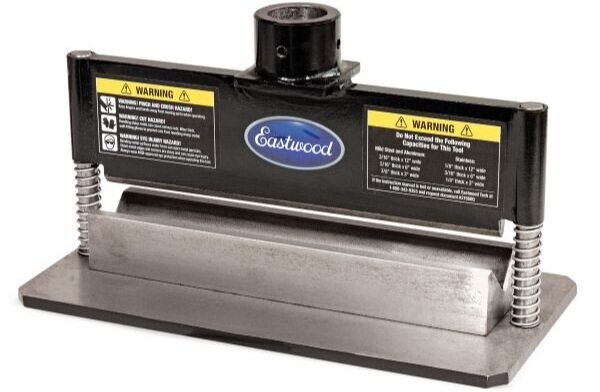
I purchased an Eastwood press brake attachment that fits my 20-ton Harbor Freight hydraulic press. The advantage over the garage-made dies that I used in a previous post is that the top and bottom dies are automatically aligned and the unit is heavy which makes it easy to use a square to align the material being bent. The downside is that the upper die is pointed rather than a piece of 3/4” round bar which gouges 1/4” aluminum.
I had calculated the bend angle to be 16.2 degrees so I used a digital angle gauge to achieve 9.2 degrees. Since both sides are being equally bent and the gauge only measures one side I divided the number by two and then added one degree for spring back. While the trig is exact it doesn’t take into account the bend radius and that the material stretches when bent. After experimenting with a few pieces I determined that the target angle should be 10 degrees and that a piece of 1/8” of scrap aluminum placed on top prevented the upper die from leaving a crease in the part.
I found that leaving the ends long allowed me to easily determine if they were parallel. Once the piece was bent I used a belt sander to remove the deformation on the sides caused by the bending process. Not doing so will result in the vice jaws only squeezing on bulges which will throw off digital readout (DRO) measurements. Worst the bulges aren’t equal which means that the largest set will act as a pivot point which can cause the part to spring upwards and out of the vice when being machined. This not not only wrecks the part, but it can create a dangerous situation. I had that happen with a previous part and I know better now.
I then drilled an M8 hole in the bracket and mounted the servo. The next challenge was to precisely determine where the the second mounting hole should be drilled. This would be difficult to achieve by measuring. Instead, I applied layout dye to the back of the bracket and used a transfer screw to scribe a short ark. The intersection of that ark and the midpoint of bracket was the exact location of the hole. The result was pretty much zero slop even before the screws are tightened.
The next step was to lighten the bracket with holes, slots and rounded ends.
The next step is to figure out how to route the wires and the air supply hose.
Headers - Almost Done
The right primaries were tacked to the flanges and the engine was pulled. This is the first time that I’ve seen it all put together and I think that it looks pretty bad ass. The next step is to fabricate the welding jig for the right header, finish welding the right header flanges and weld v-band clamps to the merge collectors.
This also gave me an opportunity to bolt up my latest revision of the serpentine brackets, spacers, pulleys and belts. I need to make a few tweaks, but I was able to get a Gates 10-rib MICRO-V FleetRunner (aka green belt) to fit.