The next step in the rear suspension upgrade was to replace everything except the lower control arm (e.g., the uprights, suspension brackets, upper control arms and rockers). The stock rockers are composed of six machined parts and six screws whereas the new rockers are machined from a single piece of 7075 aluminum. I’ve had the suspension apart many times and it was always a bit of a challenge to install the rod ends and misalignment spacers, but the tight tolerances and misalignment bushings that insert into the rod end rather than misalignment spacers that must be carefully aligned and often fall to the floor simplify the process. My contribution to the design was the addition of an integral mounting point for the anti-roll bar link. I had spent a lot of time fabricating a solution that bolted to the stock rockers, but this is more elegant and requires no additional parts.

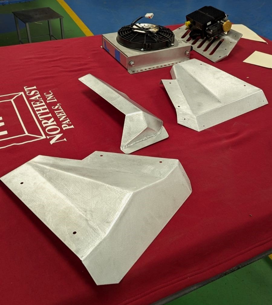
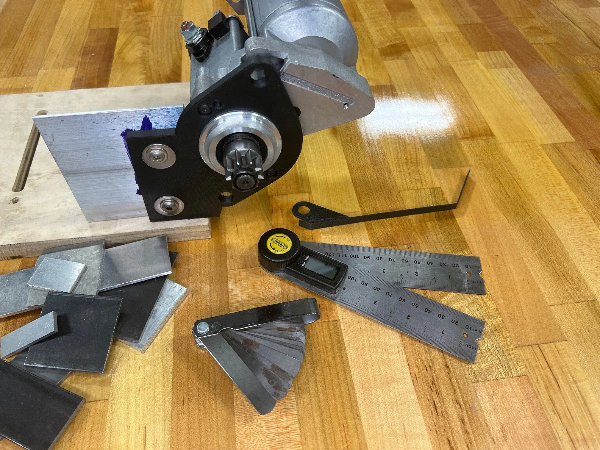
From left to right; suspension mode adjuster, rocker, misalignment bushings, rear damper center bracket and camber adjustment shim

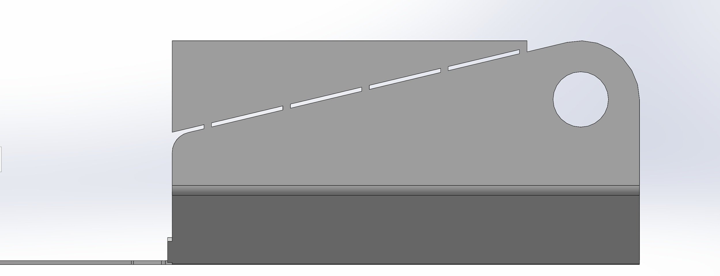
The mounting point for the sway bar link is located in the top left of rocker shown above
The stock suspension has a bit of a mismatch between the front 1.57:1 and rear 2:1 wheel:damper ratios. IMO, the crazy high rear spring rates that some people are running are due to this discrepancy and the need to have enough stiffness for the track. To address this, the new rocker has a Suspension Mode Adjuster that enables you to quickly change the ride height and motion ratio between Street Mode and Track Mode. The rocker’s Street Mode motion ratio is 1.5:1 which is close to the stock front 1.57:1 ratio. Track mode changes the rocker’s ratio to 1:1 which increases the wheel rate and reduces the ride height by 20mm (~0.8”). The suspension analysis software indicates a 500 lb. rear spring rate which, when combined with the semi-active dampers, should provide a comfortable ride on the street and aggressive handling on the track.
The Suspension Mode Adjuster captures the pushrod’s rod end. The parts are nicely machined with tight tolerances. I had to hit it with a polishing wheel to get everything to fit perfectly. Changing the suspension mode is easy; air jack the car, jack the lower control arm to remove the load on the push rod, remove the push rod’s bolt, pivot the adjuster and replace the bolt. Since all of the parts are captured by the adjuster and the rocker has built in stops there’s nothing to fall on the floor and there are zero alignment issues.
Unfortunately, the front suspension isn’t pushrod based, so Track Mode will be implemented by preloading the front anti roll bar. I’ll do another post about that mechanism when it’s finished.

Right rear upright viewed from the engine compartment side. The top piece is the upright bracket which allows shims to be slid between it and the upright to facilitate easy/predictable camber adjustment. The extension on the top right is for the toe link. This is cleaner that the stock approach and provides more room for big brakes. The bracket on the left is for motor-on-caliper parking brakes.
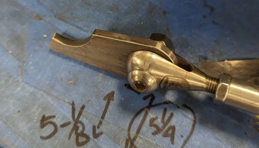
The rear roll center was 70 mm (2.8”) too high and the anti-squat was a little too aggressive. This was addressed via a combination of the previously posted custom uprights and CNC-machined brackets to adjust the locations of the lower control arm and toe link rod ends. The location of the bolts that mount to the billet chassis pieces couldn’t be moved and their heads were colliding with the rod ends. The solution was to use motorsport rod ends which increased clearance and to machine the low-profile hex-to-counter-sink adapters shown below to recess the bolt heads. Lowering the roll center reduces jacking forces and improves handling and the decreased anti-squat provides a slight improvement in traction and significantly more feel for what the rear is doing under acceleration.

The brackets for one side of the rear suspension; from left to right: forward lower control arm, rear lower control arm, toe link and toe link spacer. The toe link spacer improves bump steer. The bottom three are low-profile hex-to-counter-sink adapters.
In the stock suspension the pushrod binds on the upper control arm at full droop and the improved geometry exacerbates that issue. The binding isn’t that bad when you’re slowly raising the car via a car lift or hydraulic jack, but I winced every time I air jacked the car and they slammed together. The solution was to design a new upper control arm which, in addition to solving the binding issue, increased droop by approximately one inch.
To make all of this work National Aerospace Standard (NAS) nuts, bolts and washers were used. Their hex heads are dimpled and shorter than Grade 8 or AN bolts. This reduces weight, enables them to fit in tighter spaces and utilizes tools that are typically one size smaller. Their finish is also a lot nicer. The downside is that there’s a lot of confusing specification nomenclature, they aren’t cheap and I haven’t found a supplier that makes it easy for a garage builder to procure them.

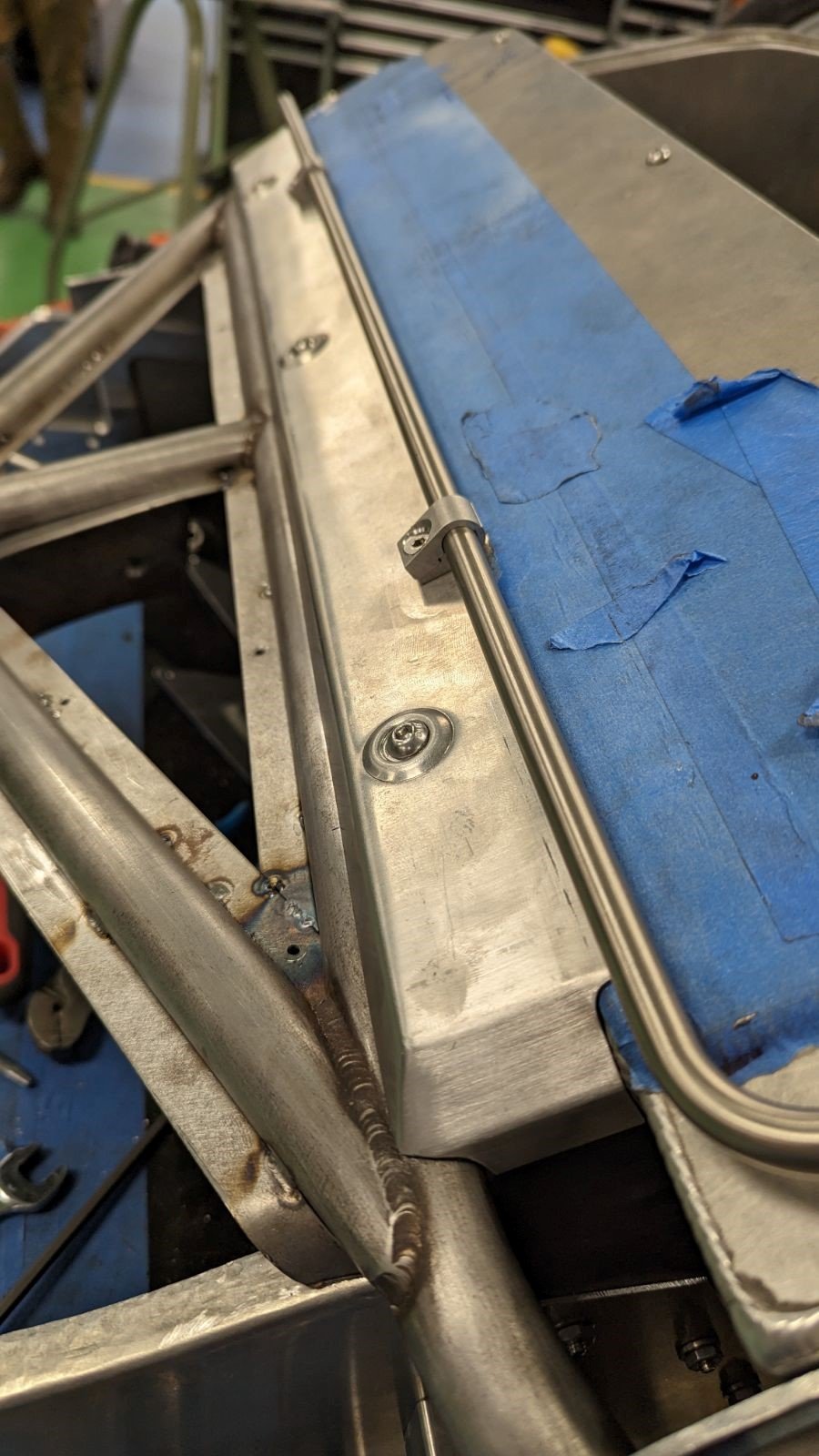
The rocker is in Street Mode (the empty hole in the rocker is for Track Mode). Note that one camber shim is installed. You can see its removal tab protruding near the toe link.

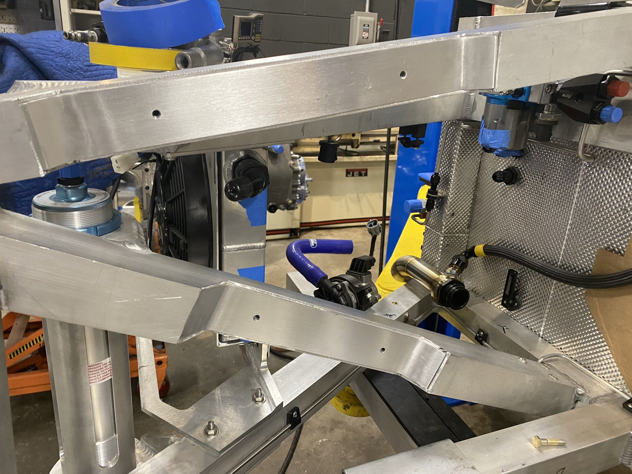
The anti-roll bar link is the light gray tube below the spring

The TracTive dampers were too long to fit between the rocker and the rear chassis billet piece so they had to be cantilevered which required a three-piece bracket. In the photo above, the center bracket is machined from 7075, the top bracket is a 3D-printed prototype and the bottom bracket which isn’t visible is still being designed.
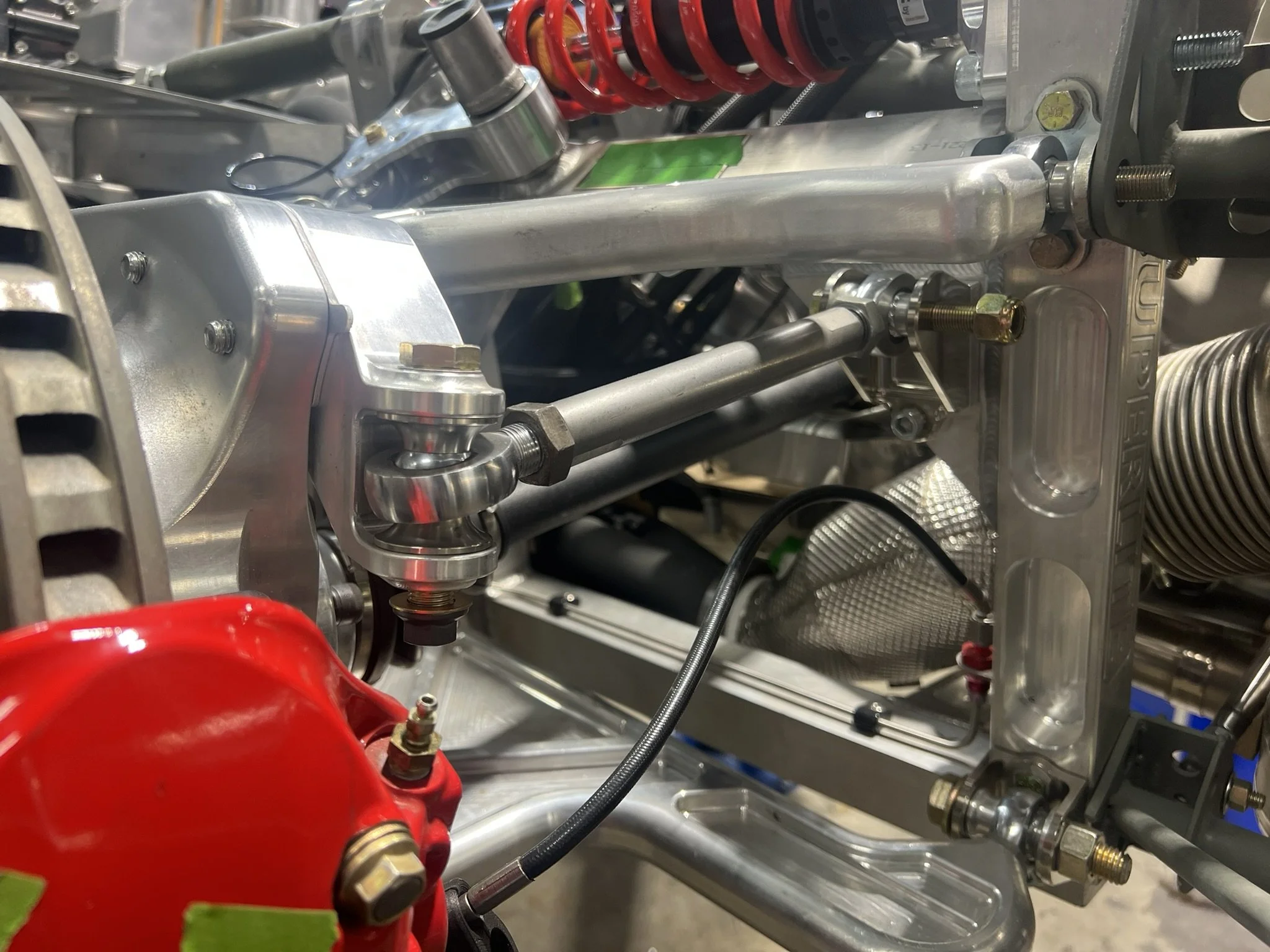
My brakes are much larger than the stock ones and I had to machine the stock toe spacer and arm to clear the banjo fitting and even then, everything was exceptionally tight. As can be seen above, the new toe link configuration is elegant and provides gobs of space.
While the front suspension was spot on, the rear suspension upgrade was a massive amount of work and I still have a few small things to finish. The benefits of the rear upgrade include:
Active dampers; each corner’s rate is independently modulated with a 5ms response time (same system used by Pagani, Donkervoort, etc.)
Engineered bump springs; provides more more progressive/manageable spring rate before max compression
Adjusted rear rocker motion ratio from 2:1 to 1.5:1 for street mode and 1:1 for track mode, giving much improved damping control
Ability to quickly switch between street and track modes (i.e. change ride height and wheel rate) via a suspension mode adjuster integrated into the rockers
Corrected rear roll center geometry, lowered by 70 mm (2.8”) which reduced jacking forces and improves handling
Increased droop by approximately 25 mm (1”)
Decreased anti-squat provides a slight improvement in traction and significantly more feel for what the rear is doing under acceleration
Shim-adjustable camber adjustment
Integral anti-roll bar mounts
Pushrod no longer binds on the upper control arm
Improved rotor cooling (upright enables rotor to be cooled from the center and tapped holes are provided for carbon fiber brake ducts)
Provision for wheel speed sensor wires to be routed in the upright
Increased toe link clearance for large brake packages
Rear toe link spacer to improve bump steer
Tapped holes to mount parking brake brackets
Motorsport-quality rod ends (high angle so they don't neck out at full droop of bump)
Cumulatively this results in a car that’s easier to adjust, is comfortable on the street and will perform better than many track-only SL-Cs.