Heater Valve Redux

HCV Delete.jpg

This is another one of those two steps forward, one step backwards situations. Two and a half years ago I created a 3D-printed bracket to mount the heater bypass valve. I spent a fair amount of time on it and it’s a slick piece, but I’m not going to use it. I’m going to create a mini museum in the garage with three displays:

  • Shelf of Lost Fame — Great parts that I designed, but I didn’t use because I changed direction

  • Wall of Shame — Parts that I mangled… there are some doozies

  • Drawer of Lame — Purchased parts that I can’t return which don’t fit, don’t work or aren’t compatible with the new direction

I decided to not use the heater valve plate for two reasons. First I’d have to remove the spider to service the valve… no way would I want to do that once the car is painted, the windshield is installed and everything is sealed up. Secondly, now that I am replacing the mechanical water pump with an electric one I don’t need the heater bypass valve which means that hot water won’t be constantly flowing through the valve. Since I don’t have to worry about heat soaking the cockpit when the heat isn’t on, it makes sense to move the valve from the rear of the car to under the dash. It will be easy to service in that location, it’s more protected than the engine compartment and I don’t need to run control wires to the rear of the car.

The straight-through heater valve is easier to mount than the bypass version. The four posts can be tapped for 6-32 screws. I fabricated an aluminum plate, 3D printed a spacer and mounted it to the aluminum tube that was recently welded to the top of the foot box. The lightening holes in the bracket don’t save much weight… I just like using Hougen hole cutters because they cut metal like butter.;-)

I bought several heater hoses looking for one that was flexible enough to make the required bends without kinking and I found the nylon reinforced silicone hose offered by Vibrant Performance to be good to work with.

IMG_7950.jpg
IMG_7953.jpg

Radiator

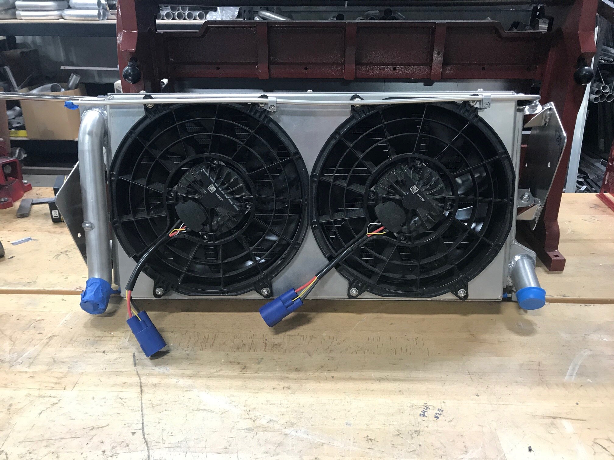
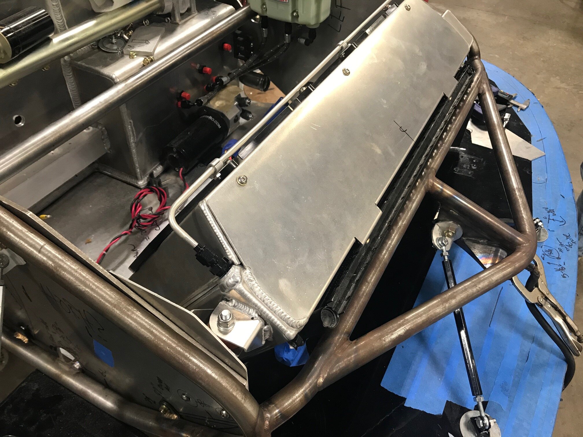
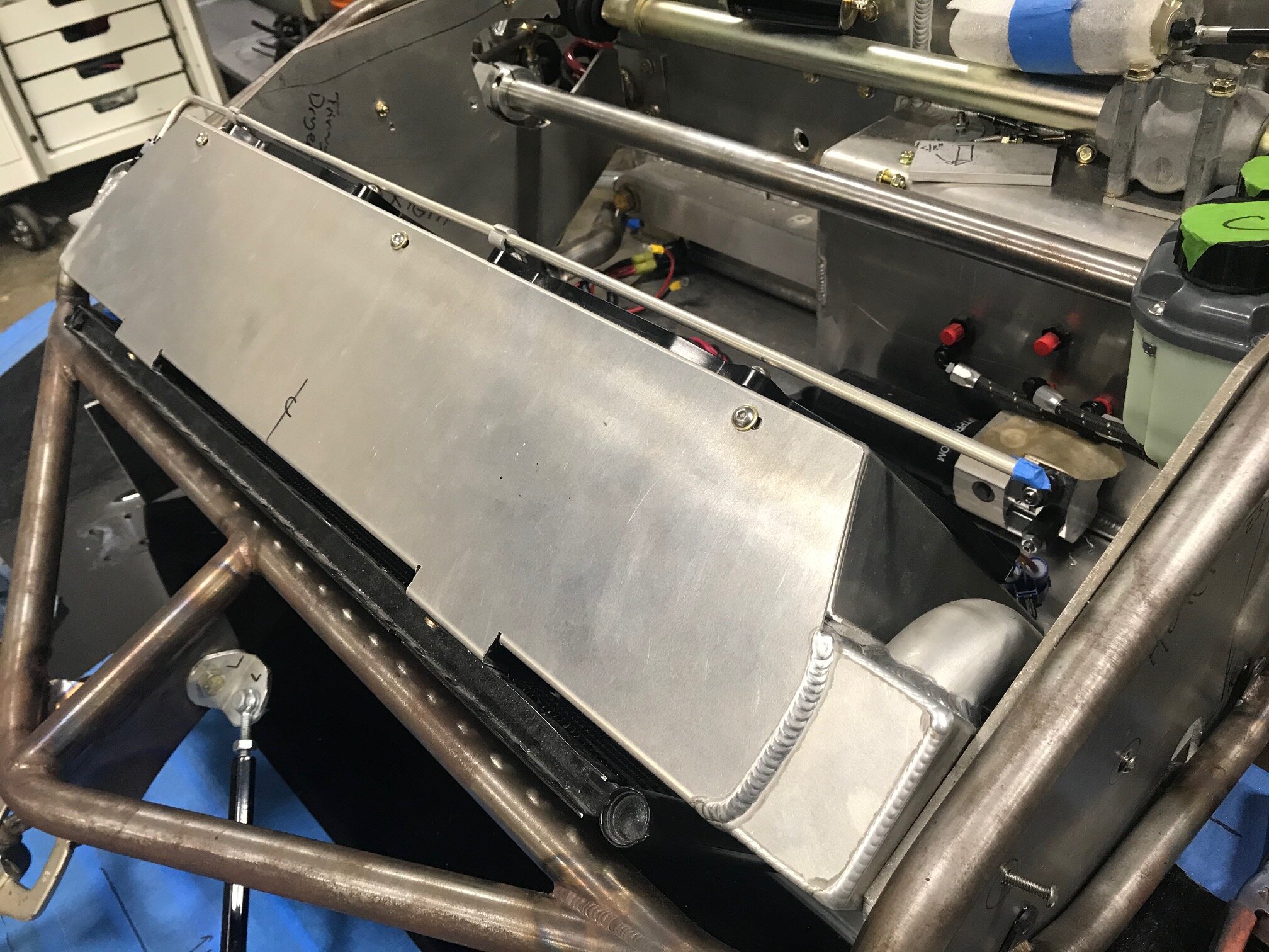
I spent of time a lot of time time working on the stock cooling system. I upgraded the fans, made a shroud and spent a lot of time designing 3D-printed brackets to mount the condenser. I was really impressed with my brackets until another builder pointed out that attaching the condenser to the floor wasn’t a great idea because the both it and radiator should be isolated from the chassis. D’oh!

I started doing some research which, in my case, can be dangerous. I decided to start from scratch with the following improvements:

  • Complete vibration isolation

  • Higher quality core

  • Slightly larger core

  • Move inlet from bottom of core to top

  • Move outlet from top of core to bottom

  • Move the bleed port from the high-pressure to the low-pressure side

  • Air-tight shroud with proper spacing from radiator

  • Highest quality fans available

  • Integrated mounting tabs for the condenser

  • Hard tube from bottom of radiator to inlet at the top

  • No brass parts

Vibration Isolation

Isolation dampers; stock/black ones on left, new/red ones on right

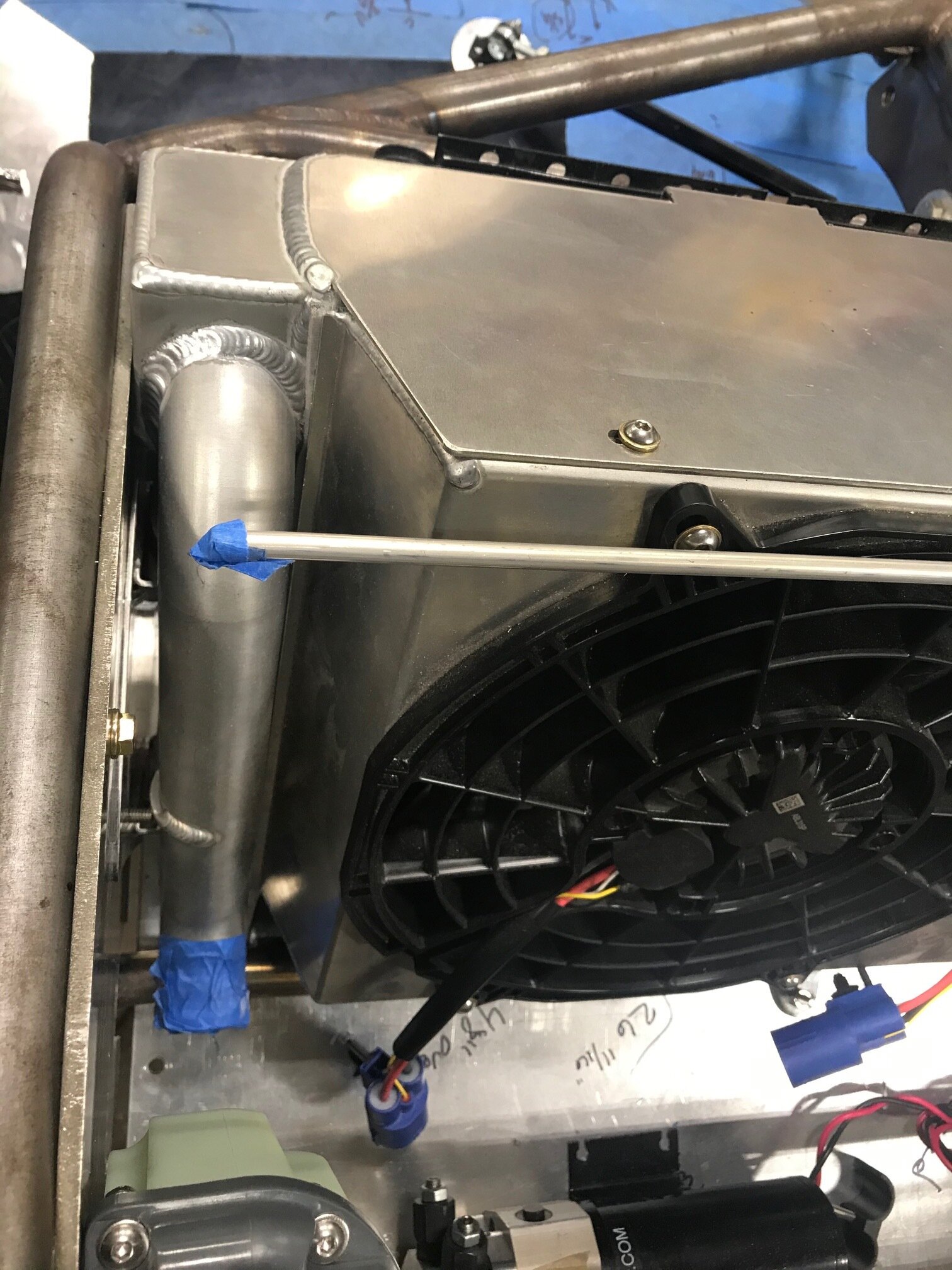
The stock radiator was well made, but it was jammed so tightly between the vertical supports that it was almost a stressed member and the provided grommets were laughable. My solution was to support the new radiator with two vibration-sandwich mounts per side. The picture compares the stock grommets (black) on the left and sandwich mounts on the right (red). Now, you’re probably thinking that the large mounts will reduce the size of the core. Well it just so happens that side tanks don’t need to be wide to be effective. In fact, they can be a lot narrower than the OD of the 1.5” inlet and outlet tubes. As can be seen in the picture the picture below, the side tank is narrow at the top to accommodate the mounts, but wider at the bottom to support the outlet tube. This approach results in a wider core than the stock radiator and reduces weight (the smaller tank uses less aluminum and stores less water). The downside to this approach is that it costs more to fabricate and it’s more difficult to prevent air from slipping around rather than through the radiator.

IMG_7942.jpg

C&R Racing

Will and I visited C&R Racing’s booth at SEMA and we were impressed. They are the same guys that made the radiators for the Raver cars and for Howard and I found them to be professional and good to work with. After filling out a form to specify the requirements we went through several CAD iterations. They spec all dimensions and every part down to the washer. I’m ordering heat exchangers from them for air-to-water intercooler.

Fans

C&R recommended SPAL 11” brushless ABL315P drop-in fans. They are the highest performance fans that Spal provides, but there isn’t much information on them as they are only available from resellers who bundle them with a fan shroud (see spec sheet below). Bundling makes it difficult to figure out the actual cost of the fan, but it appears that they cost a little over $400 each. You’ll also need something to control the fans which in my case will be MoTeC.

The drop-in-style fans result in really nice packaging. I’ve wondered if they should have put a couple of flaps in the shroud, but I assume they know exactly what they’re doing. If not, I’ll send the shroud back to them to have flaps installed.

The stock radiator has a brass drain cock which promotes electrolysis in aluminum. I replaced it with a zinc-plated steel drain cock which will be connected to a drain tube drilled through the floor.

Monocoque Modification

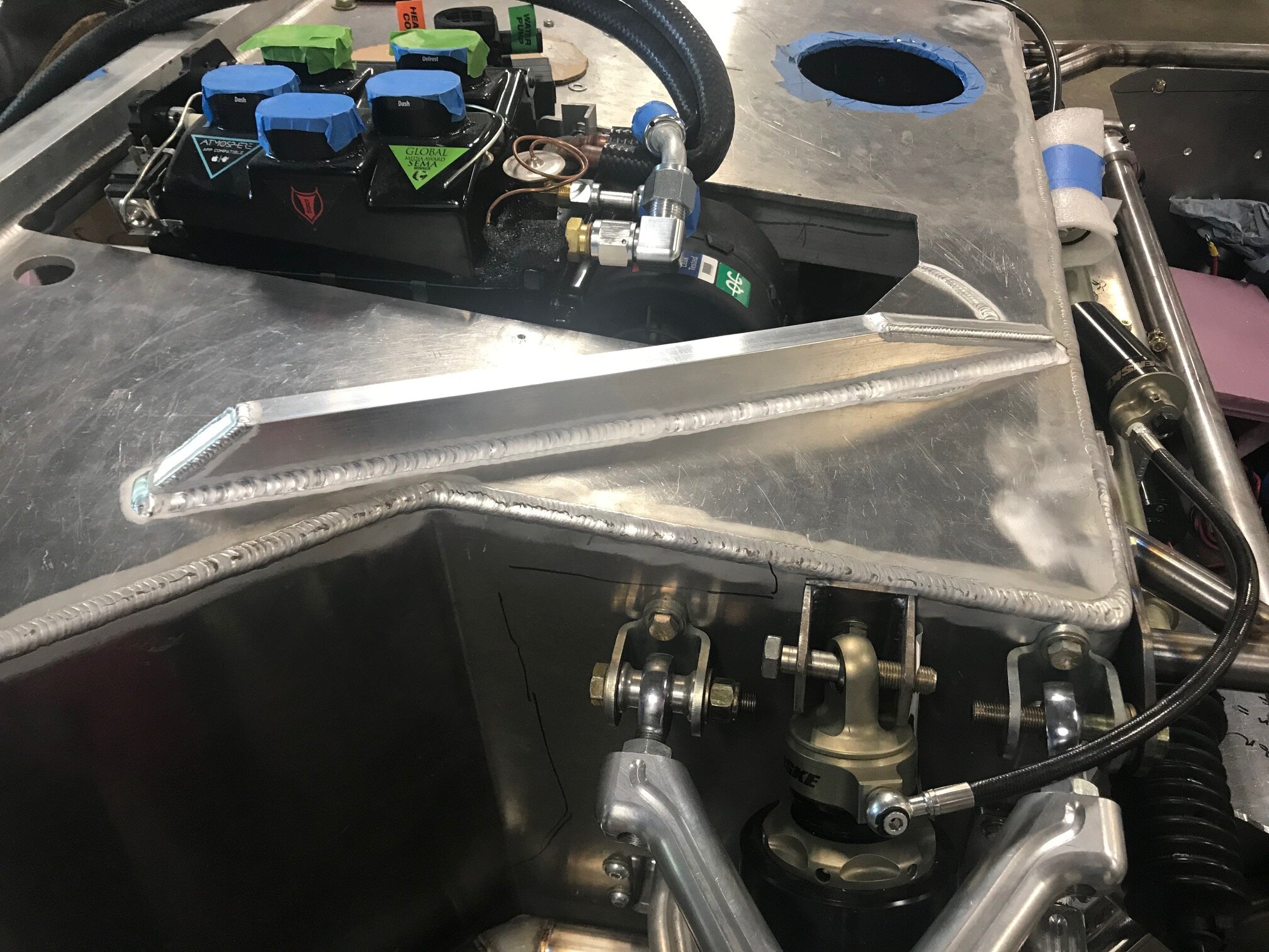
In a previous post I cut a huge hole in the top of the monocoque / foot box to fit the Restmod Air evaporator. Although I have the optional removable side impact bars which add a lot of rigidity (they have welded steel plates that pick up the upper control arm mounts and the upper shock mount) I wanted to ensure that I wouldn’t have a structural problem.

The first step was to fill in part of the circular access hole with 1/4” plate. As can be seen in the photo below the edges were chamfered to get good penetration and a flat weld. Once that piece was welded, a 3/4” x 1-1/2” x 1/8” tube was welded to the top of the monocoque. The right corner is now rock solid.

Throttle Body

Two steps forward, one step back… again. I have several issues with the induction system. The induction tube was hitting the tail and created a small crack in it. The ID of the weld flange mounted to the supercharger snout created an abrupt transition and it was too close to the supercharger’s o-ring — we don’t wanting that getting sucked in by accident. The LS7 throttle body was large and in the way and there no straight section long enough to mount a mass airflow sensor (I might have a blended MAAF/MAS tune).

I wasn’t sure what to do about it until Allan mentioned pointed out how much smaller the LT5 throttle body was. It’s dimensionally much smaller (see photo below), 32% lighter (2.24 vs. 3.29 lbs.), has a larger diameter (90 mm vs. 95 mm ) and it was designed for a supercharged rather than a naturally aspirated engine. Since I ‘m using a MoTeC ECU there won’t be tuning issues due to a different throttle body.

Of course, I mistakenly ordered a ported LT4 throttle body from Katech which means that I have I now have three throttle bodies. All too often, the third try seems to be the charm! In any event, if anyone needs a LS7 or an LT4 throttle body I’ll cut you a deal.

I spent many hours searching for the correct weld flanges. There are a lot of LT5 adapters out there, but I couldn’t find anything that met my requirements so I designed custom ones. Both have an internal recess to ensure that tube remains concentric with flange ID. The supercharger snout flange smoothly tapers the 4” tube into the snout and the throttle body flange has a groove for an o-ring. One-off CNC parts are spendy and can have long lead times so I 3D printed a couple of prototypes. As can be seen in the photo below, the fit was tight enough to hold it in place so long as you don’t bump it. Abe was able to use them to mock the tubes, but he suggested that I beef up a few areas to prevent warping when welding.

The next step is to find someone to CNC machine them… I’ve been thinking about buying a machine for years, but that might push my wife over the edge. Once I get the the flanges machined and the tube between the supercharger snout and the throttle body tacked in to place, I’ll need to scallop the upper 2” x 2” chassis rail to enable the tube to clear the tail.

Corn Juice

I plan to run both 93-octane pump gas and E85. E85 is a blend of 85% ethanol and 15% gasoline by volume. If you’re wondering why I want to run my car on corn juice and what it takes to do so, read on.

Corn is Cool

When fuel vaporizes in an intake system, it has a cooling effect referred to as the latent heat of vaporization which is expressed in BTUs per pound; ethanol is 396 and gasoline is approximately 150. So what does this 2.6x increase in cooling equate to?

Apparently motors will typically run 15-20 degrees cooler on E85 than gasoline. Given that one of the largest challenges with a mid-engine car is heat management in the engine compartment, this is a very desirable benefit for a SL-C.

In addition, a cooler combustion charge has two significant performance benefits. First, a cooler combustion charge is more dense which improves volumetric efficiency, which improves cylinder pressure which improves power:-) The performance gains are significant on high-boost supercharged or turbocharged engines which heat the intake air as a negative side effect of compressing it. This is exactly why intercoolers are used.

Secondly, when E85’s cooler combustion charge is coupled with its higher octane rating (typically 105 or above), it becomes very resistant to detonation which means you can run more boost, more compression, more ignition advance, or all three.

Fuel Consumption

In a previous post I discussed my fuel pump requirements assuming a Brake-Specific Fuel Consumption (BSFC) of 0.65 at wide-open throttle. However, ethanol only contains 82,000 BTU per gallon whereas gasoline contains approximately 115,000 BTU per gallon which means that ethanol has a higher BSFC. Since ethanol contains 40% less BTUs per gallon you need 40% more fuel to obtain the same power level! The following are rule-of-thumb BSFCs for different fuels in a forced-induction application:

  • Gasoline: 0.60 to 0.65

  • E85: 0.84 to 0.91

  • Methanol: 1.80 to 2.00

So my engine running on E85 at wide open throttle (i.e., 1,000 HP) requires 152 GPH. My high-pressure pump will handle that volume, but I’m now considering a low-pressure pump upgrade. I’ll also need to determine if I need to upgrade the fuel injectors.

Ethanol Blend

Ethanol requires more heat to vaporize than gasoline, which can cause cold start problems when the temperature drops below 20 degrees F. To solve this problem, the Federal Government allows up to a 30% gasoline content in E85, which essentially makes it E70. Apparently cranking in cold climates is the primary reason ethanol is blended with any gasoline (i.e., in Brazil pure ethanol is used).

Most pump gas is blended with 10% ethanol (E10) so depending on what was in the tank when I filled up, what I filled up with and the time of year, I’ll be running om something between E10 and E85.

Ethanol Content Sensor

Small changes in the amount of ethanol content will cause air/fuel ratio changes that have a significant effect on vehicle driveability. As the amount of ethanol in the fuel is decreased, the mixture becomes richer. To enable the ECU to change the tune on-the-fly based on the amount of ethanol I installed a ethanol content sensor (Continental 13577379) which is apparently widely used by OEMs and tuners. The inlet and outlet are straight aluminum tubes with a raised ridge and I wasn’t sure how to connect an AN fitting to it. Fortunately, Fore Innovations (and I assume others) offers multiple AN Male to EFI Female Adapters.

To install them, you carefully remove the retaining clip, slide the adapter on the tube until it hits the ridge and reinstall the clip. The clip is on the far side of the ridge which pulls the adapter into the ridge locking it into place. This applies pressure to an internal o-ring that is sandwiched between the adapter and the ridge, thus creating a leak-free interface..

I considered mounting the sensor to the backside of the aluminum heat shield between the exhaust manifold and the chassis, but I wanted to be able to remove the heat shield without touching the sensor. So I fabricated a bracket to mount it under one of the 2” x 2”s.

E85 Compatibility

E85 is much more corrosive than gasoline so everything in in the fuel system must be compatible; fuel pumps, fuel lines, injectors, fuel tank, fittings, filters and thread sealant. Fortunately I’m using high-end XRP fittings and fuel lines that are compatible, I’ll need to replace the thread sealant on the gas tank and the low pressure pump because they used tapered/NPT fittings rather than ORBs.

Fuel Flow

I received several questions on my build thread regarding fuel flow capacity.

What GPH / LPM is the pump rated at in order to support their 1800 hp?

Fuelab’s marketing indicates 190 GPH (720 LPH ) at 45 psi (3.1 bar). However, every pump has a serial number and comes with a printed certification sheet. The following is a scan of mine. Looking at the results, my pump flows enough fuel for 1,800HP at around 75 psi, assuming that gives you enough boost headroom.

What low pressure pump will you run to keep the Radium surge tank full?

I'm a little over 1,000HP so I don't need to worry about feeding a 1,800HP monster. Assuming a Brake-specific Fuel Consumption (BSFC) of 0.65 at wide-open throttle (WOT)

GPH at WOT = (1,000 * 0.65) / 6 = 108.3

I used a Holly 12-125 because it worked well for my layout (it's vertical) and it seems to have a good track record. It is rated at 125 GPH free flow and 110 GPH at 7 PSI. So, In theory it can keep pace with WOT consumption if the pressure is in the surge tank is around 7 PSI. That said, I can't imagine applying 1,000HP for long in a SL-C, particularly in a sweeper that starves the low-pressure pump.

Radium's documentation "generally recommends a [lift] pump with a rated flow of 400+ LPH." That's 106 GPH which a little less than the Holly's spec.

Surge Tank and Fuel Filter

I spent a lot of time looking for a fuel pump with the following requirements:

  • 1,000+ HP; it’s gotta have the juice.

  • Brushless: Heats the fuel less and consumes less power.

  • PWM’able: No way do I want to be sitting at a light with the pump pushing over 120 gallons / hour at 42 psi. That will heat the fuel and if something comes loose I want to be flowing as little fuel as possible.

  • In tank: Reduces external plumbing and keeps the pump cool.

  • Flange-mount: No brackets, clamps, hoses or wires dangling inside of the tank.

  • Ethanol Compatible: More power and lower operating temperature.

While many pumps met most of the criteria, the brushless/PWM’able combination was the limiting factor. At some point during my search Radium announced a surge tank designed for the FUELAB 92902 which met all of my criteria. It’s rated to 1,800HP and has an integrated motor controller. This allows me to simply connect it to one of the PDM’s PWM outputs.

Great! I immediately ordered one… not so fast. Apparently FUELAB, chasing bigger HP numbers, changed the height of their pump twice which required Radium to change their surge tank twice. So, after over a year of waiting, I finally received the pump and the surge tank.

IMG_7728.jpg

Radium provides a filter which bolts to the bottom, an o-ring and a retaining ring with bolts — so about three minutes to install it into the surge tank.

I fabricated an aluminum bracket for the surge tank and attached it to the 2” x 2” tubes with six 1/4”-20 nutserts, two of which capture the surge tank. Four additional 1/4”-20 nutserts mount the surge tank to the bracket. I will fabricate a heat shield to protect it from the exhaust manifold.

Fuel filter mounted

Fuel filter mounted

I also mounted my super trick fuel filter which I wrote about. Man, it feels good to get that out of the box and mounted to the car!!! If you’re wondering what the trio of holes are to the right of the fuel filter are, they are specifically designed to reduce harmonic engine vibrations from disrupting fuel flow through the filter OR I mounted the filter in the wrong place and now need to weld the holes shut;-)

Front Vent 1.0

I’ve decided to move forward with the modifications to the side of the car discussed in a previous post. The first step was to refine variant 2.6. The image below shows thee vent height options.

Vent-Height-Variations.jpg

A1: Keeps the stock vent height and is the easiest to implement because no changes are required to the nose or door.

A2: Extends the vents upwards, but leaves about an inch of body between the vents and the nose and tail split lines. The door and the nose need to be modified, but the AeroCatches which latch the nose and tail remain in their stock locations. While the body between the vents and split lines makes latching easy to implement, it clutters the aesthetics.

A3: Extends the vents upwards all of the way to split lines. This results in the cleanest aesthetics, but it requires the latching locations to be re-engineered and is a lot more work than the previous variants. Funny how that always seems to be the case.

So which am I going to do? A3 — the most involved of course.

Today I made some initial cuts to implement the front vent… there’s no going back now! The AeroCatch and rear locating pin (A) were completely removed. Filling the curved vertical section (D) will be easy. I just need to bolt a curved non-stick piece of plastic to the outside and patch from the inside.

IMG_7712 Annotated.jpg

I left a portion of the flange that the nose sits on in place because the bottom side of the nose flange needs to clear the door hinge and the side of the spider when it is raised and lowered and something needs to seal the nose from the exterior. This flange will likely get cut back further and I’m wondering if I should create a large fillet to blend its underside into vertical section D.

The AeroCatch will fit into section C if it’s oriented transversely. However, that orientation places the pin more inboard than desirable which may cause the strike pin to scrape the side of the spider. The factory body fitment had that issue on the right side and the scrapes can be seen in B. For this reason, I’m going to replace the AeroCatch with a Quick-Latch QL-35. Even if I trim the flange off of the end of the AeroCatch, the center of the pin is 1.5” from the edge whereas the Quick-Latch is 0.9” with the flange in tact. In addition, the Quick-Latch installs with a single 1.25” hole saw whereas the AeroCatch requires a more complex oblong cutout and six mounting holes. Each Quick-Latch is rated for 500 pounds, so they should be more than strong enough.

The biggest question at this point is what to do with piece C. If left as is, I will need to reinforce it (glass it to the curved vertical piece) and close the curved back edge (red lines). IMO it will look bulky and getting the back edge finished properly will be tricky. Another option is to raise piece C. The Quick-Latch requires a minimum depth of 1.2” which would allow me to reduce the distance to the part line by at least half. Getting the curved back edge to look right would be easier because it’s smaller and less visible. That said, I’d need to make a simple mold. I ordered a set of Quick-Latches and I’m going to reflect on things before cutting any more.

The door consists of an inner and outer shell which are bonded together at the factory. Fortunately, there is a fair amount of space between the two pieces which allowed me to cut the outer shell. I ground the dark-gray adhesive on the front edge because I assume that epoxy/fiberglass is stronger and I’m not sure how well the adhesive would blend with fiberglass or hold paint. As can be seen in the profile picture, there is plenty of room for epoxy/fiberglass to add strength and micro balloon mix to create the profile. The top edge of the door is thin near the top of the cut, but I can easily add fiberglass to the inside of the door there.

Man Bag

CC131253_hi.jpg

I took a six-week vacation with the family and, fearing build withdraw, I made a man bag to bring some electronics along. Needless to say my wife wasn’t happy — something along the lines of “NFW are you bringing that!”.

Joel made a bench harness so that I could start to get my brain wrapped around the MoTeC display, Power Distribution Module (PDM), keypad, rotary keypad, Dual Half Bridge (DHB) and CAN bus. The test harness is first rate; Deutsch connectors, Raychem DR-25 sheath, labels on everything and detailed documentation.

My plan is to focus on the basics and leave all of the complex ECU and tuning stuff to the pros. Even so, MoTeC isn’t geared for DIY’ers, so Joel is providing tutoring lessons via a remote desktop application— my kids think it’s hilarious that the old man still needs tutoring.

One of the primary objectives with a MoTeC setup is to replace as many physical fuses as possible with PDU outputs which have configurable current limits, automated retries, logic and logging. For this reason, the harness powers the display via a PDU output. The first step was to configure the name of the output. Like software, it’s a good idea to provide robust names. Since it’s part of the bench tester and it powers the C127 display, the keypad and a spare power connector, I named it “Output.BenchTester.C127/Keypad/Spare”. To power it, I simply created a condition as can be seen in the snippet from the PDM Manager below. When then PDM has power, the display, keypad and spare power connecter have power.

MoTeC_01.jpg
grin635_hi.jpg

I didn’t get very far with things, mostly because I had a poor internet connection which made the remote sessions difficult. However, I was able to get the keypad buttons to activate turn signals, the hazard and to activate the DHB.

Now that I’m back home, I’m going to get things kicked into high gear!

Side Scoop

SLC-Sidemods.jpg

The SL-C has been around a while and still looks great, but I’d like to modernize it a bit. Before I embark on changing the tail as discussed in a previous post, I’d like to go through the design, CNC cut male buck, fine tune buck, make female mold, make part, blend part into body process a couple of times on simpler parts. Specifically, the rear side scoop and roof scoop.

IMO the rear side scoop is a little small and likely doesn’t capture a ton of air — that said, I’m primarily focused on aesthetics. So I want a larger vent and to dish the side of the car like many modern cars. While dishing the doors would look great, that’s a lot more work than I want to even consider.

I’m also thinking about changing the roof scoop. I’ve always had mixed thoughts about it ranging from it’s cool to it’s a bit of a bubble sitting on top of a bubble. I’m thinking about shaving it off or making it more aggressive (i.e., rectangular). I was leaning towards shaving it because it’s cleaner and I didn’t think it was very functional… that discussion led to pnut’s recent post which indicates that at road speeds it appears to work pretty well.

Kevin did such a great job on the tail that I had him do a bunch of 2-D renderings. Here’s a bunch of variants.

Variations--Rear-Vent.jpg
Variations--Roof-and-Front-Facia.jpg

Oil Reservoir Filler Completed

I finished filler for the oil reservoir discussed in a previous thread. I replaced the black oxide screws with black anodized aluminum ones because I didn’t want them to rust and I created a design for the cap and had it laser etched.

The oil reservoir’s fill cap was cut off and replaced with a -16 AN weld bung. -16 fittings are huge and they were too close together to use a short piece of hose, so I had to create a bigger loop than I originally anticipated. I considered using a short piece of hard line, but I figured that the body would flex more than the chassis.

Since a dipstick won’t work, I bought an oil level sight tube kit from Peterson Fluid Systems which required more welding. I didn’t like how far the tube projected from reservoir so I replaced the female ORB weld bung and male AN adapter with a male AN weld bung. Lighter, half the parts and it sticks out less.

I spent a couple of hours trying to figure out how to fit the scavenge filter specified by Daily Engineering. It’s huge (9.7” x 2.5”) and it requires large -16 fittings. If the oil reservoir were located in front of the rear tire it would be a lot easier, but it’s against the firewall and it’s really tight. I found an XRP filter that’s 3 inches shorter so I’m going to see what Daily thinks about using it.

Tow Hook

And most recently abrasive…

I cut the the front tow hook out of 1/4” cold rolled steel. At two hours and 42 minutes it was by far the longest cut that I have done. I was a bit nervous about having an issue in the middle of the cut which would waste a lot of abrasive not to mention the material because during a previous cut the Wazer stopped cutting all of the way through a piece of 1/8” stainless steel.

When this happens the water jet and abrasive bonces off the material in the direction opposite to the cutting head’s motion. Unfortunately the seam between the lid and the sides is not well sealed and some water and abrasive will escape. If you don’t catch this right away you’ll have a bit of a mess to clean up. While the mess is manageable, water will drip down the side and into the abrasive hopper which wrecks it (i.e., makes it lumpy which will cause a clog). I scooped all of the wet abrasive out using a specialized tool… I know that it looks like a serving utensil, but I would never use a kitchen implement in the garage;-)

The cutting stream’s bounce back when piercing doesn’t case any issues. I assume this is because it bounces back vertically into the cutting head.

After running a test I determined that the abrasive flow rate was too low so I emptied all of the abrasive and used compressed air to ensure the abrasive feed tube was clear. After that everything worked fine. As can be seen in the picture below, the cut quality was outstanding. The cut consumed a whopping 53.4 pounds of abrasive. While that seems completely uneconomical, that’s $76.89 if you purchase by the bucket and only $24.03 if you purchase by the palette. Even the higher bucket price is about half of the minimum cut fee around here.

I cleaned up the edges with a mini sander and sprayed it with some rattle-can red (I'll powder coat it later). The short soft strap keeps the metal hook from marring the hook or diffuser.

A couple of takeaways:

  • Per the manual, stay in the same room as the Wazer when cutting. When the water jet is bouncing off of the material is makes a different sound which will alert you to look at it. Unfortunately, the piercing operation sounds the same so you need to look at the LCD panel to determine it’s piercing or cutting. If it’s cutting, you have an issue.

  • Wazer should have designed a channel into the top of the abrasive hopper so that water dripping down the side doesn’t contaminate the abrasive.

  • Wazer needs to add a feature that allows a cut to be restarted at a given place. If this cut had failed like the prior one did, it would have wasted over $100 of material and abrasive.


Pressure Regulator

I converted the fuel rails from a deadhead-return-style to a flow-through-return-style configuration to better support my power levels. While doing this I replaced all of the barbed fittings with AN fittings. Most SL-C builders mount the pressure regulator to the firewall or chassis, but I decided to mount it between the fuel rails on the supercharger. This results in less hose and I think it looks cool because it fills in an otherwise empty space which is visible in the rear window. That said, it was a lot more work than mounting it to one of the standard locations with the provided bracket.

The primary challenge was figuring out how to securely mount the regulator so that I could use hard fuel lines. There are two casting holes in the intercooler which I tapped for 1/4”-20. I then used 1/8” aluminum to fabricate the mounting plate which provided an opportunity to use my dimple dies. Yeah, I know they’re more commonly seen, and often overdone, on hot rods, but I think they’re cool. Both the aluminum monocoque and the dimple die originated in the aviation industry, so they aren’t out of place. Abe did a nice job welding it together.

Self-adhesive 1/4” rubber was used to pad the plate above the cast boss for the vacuum reference port and to help dampen vibrations. This finalized the height of the plate and two aluminum spacers were turned on the lathe to fit between the holes tapped into the intercooler and the plate. The two extensions at the back of the plate are wedged under the supercharger and are intended to help keep the plate in place.

Abe had two pressure regulators from Fore Innovations; a F1i which is two tone (raw aluminum and black) and a F2i which is all black. I prefer the appearance of the former, but the latter has superior internals, specifically a ceramic/stainless valve and a fluoropolymer coated spring. After confirming with the manufacturer, we swapped the internals.

Fuel pressure gauges are bulky. This normally isn’t an issue, but mine is on display in the window so I spent several late nights looking for a thinner one (see comparison picture below).

I wasn’t able to remove the 1/4” NPT plug from the vacuum reference port. Worrying about stripping something in an important part is one of the most stressful parts of building a car… and the supercharger is both important and expensive. I tried using a hex-bit socket and a 3/8” impact gun to no avail. I then made a simple heat shield (a hole in scrap aluminum) to protect the paint, heated the plug with a torch and tried again to no avail. If it was going to strip, I wanted Abe to be vested so I let him deal with it ;-) He heated and wailed on it with the 3/8” gun and it didn’t budge. The last attempt before pulling the super charger off and drilling it was more heat and a 1/2” impact gun. Fortunately, that worked! I replaced the plug with a stainless steel barbed fitting.

The fuel lines were fabricated out of aluminum. I’m going to look for a thinner vacuum line, but this part of the car is done until final fit up. The next step is to install the surge tank, high-pressure pump, E85 sensor and fuel filter between the fuel rails and the low-pressure fuel system.

Front Sway Bar Drop Link Redo

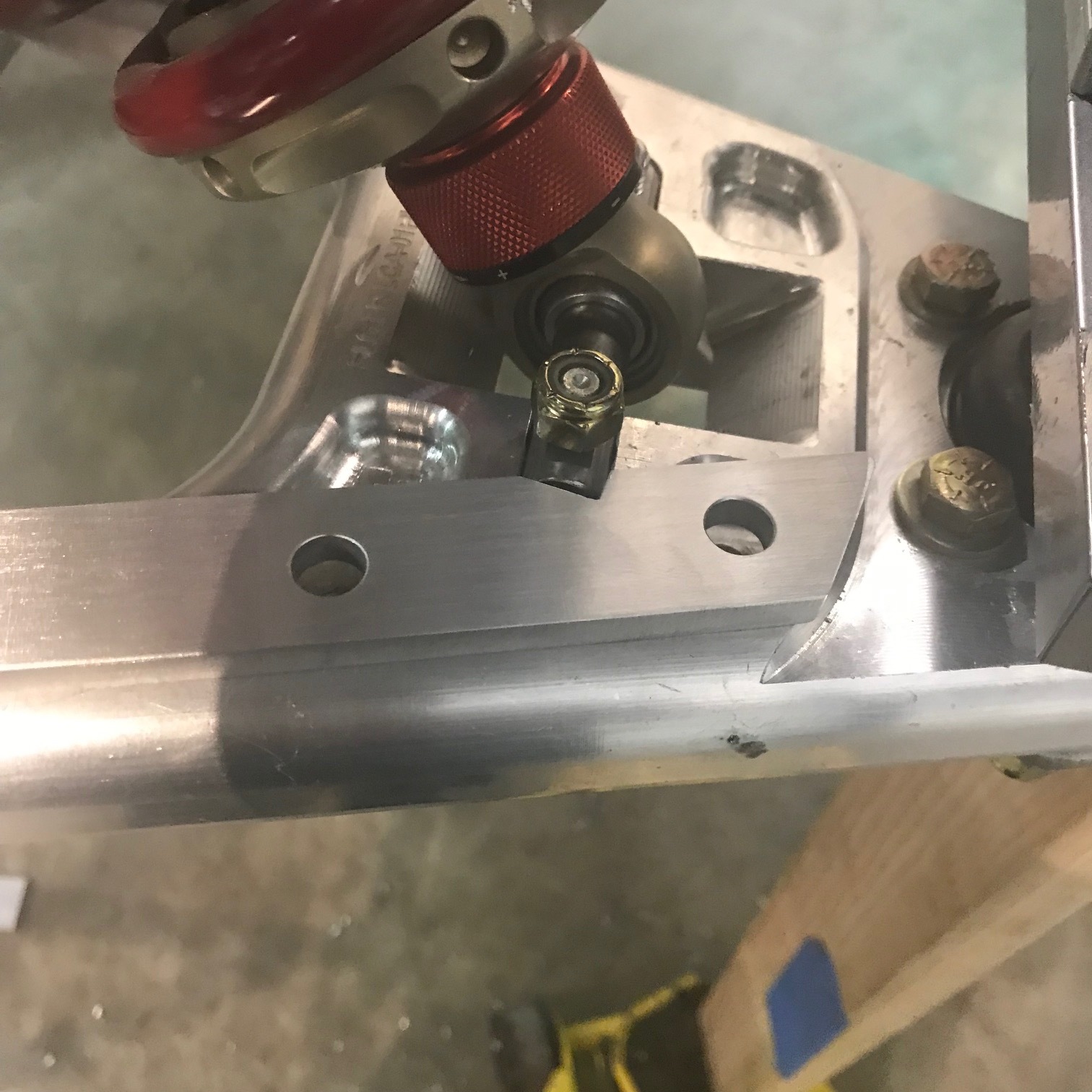
In a previous post I replaced the front sway bar that was mounted to the top of the monocoque with one that’s mounted to the nose tube structure. Although the drop links are a lot shorter, they connect to the lower control arm in the same location. However, I replaced the stock clevis with a custom chromoly bracket. The clevis was mounted with a single bolt that focused the drop link’s forces between the shock mounting pin and the chassis. The bracket distributes these forces outbound towards the hub. It is mounted with two bolts; one closer to the shock mounting pin and the other between the pin and the hub.

The pockets machined into the control arm are great to look at, but they’re a real pain in the ass when you want to mount something because you need to be careful where the holes are located. In particular, you need to avoid the chamfer unless you’re going to machine the hole on a mill. As shown in the picture below 3/8” holes were drilled into the pockets that straddle the shock mounting pin. I fabricated a 1/4” aluminum spacer to pad the bracket above the shock mounting pin (the notch shows where the interfere is). On the underside there is no room in the pocket for a bolt head, let alone a washer, so I fabricated plates out of 1/8” chromoly to span the pockets.

Intercooler Swirl Pot and Oil Filter

Custom swirl pot for the intercoolers

Custom swirl pot for the intercoolers

The intercooler system needs a reservoir, a way to add coolant and a way to bleed air. I decided to combine all three into a swirl pot. A swirl pot de-aerates coolant by swirling it around the inside of the pot as it flows from top to bottom, allowing air bubbles to break up and rise to the air pocket under the cap. The swirling action is created by aligning the inlet and outlet to be tangential to the inside diameter of the pot (if you look at the swirl pot above you will see that the fluid will swirl in a clockwise direction). The system is filled until the swirl pot is about 2/3 full to ensure adequate space for the coolant to de-aerate, while also providing a sufficient volume of coolant in the swirl pot to prevent pump cavitation.

It was a fair amount of work to fabricate the parts and a lot of welding!

While I’m going to hide the stuff I don’t like (e.g. electrical, coil packs, etc.), I want the cool parts of the key systems to be visible. With that in mind I located my super trick oil filter mount to be symmetric with the swirl pot in the rear window. This location accommodates a 5” tall filter element and enables me to easily check for debris through the view port.

viewport.png

I’m looking for a weld on sight glass like the one shown here for the swirl pot. If you know where to get one, let me know.

Nose Box 1.2

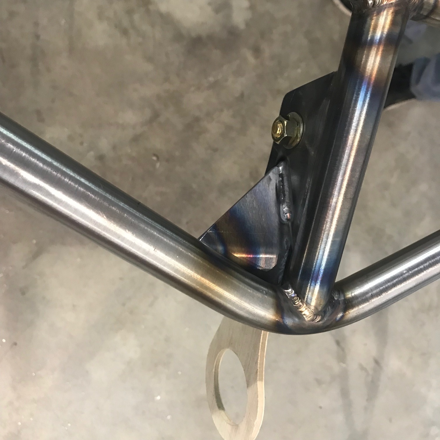
The tube frame around the nose box is almost done. As you can see in the picture below diagonal tubes were added to mount the sway bar, four 1/8”-thick tabs were added to each side to mount the vertical aluminum panels, tube gussets were installed where the top tubes meet the monocoque and a 1/8” plate gusset was was added to the tow hook bracket. The next step is to add two tube that connect sides; one on the floor behind the radiator and one at the top near the monocoque and four gussets to reinforce the bar that crosses in front of the radiator.

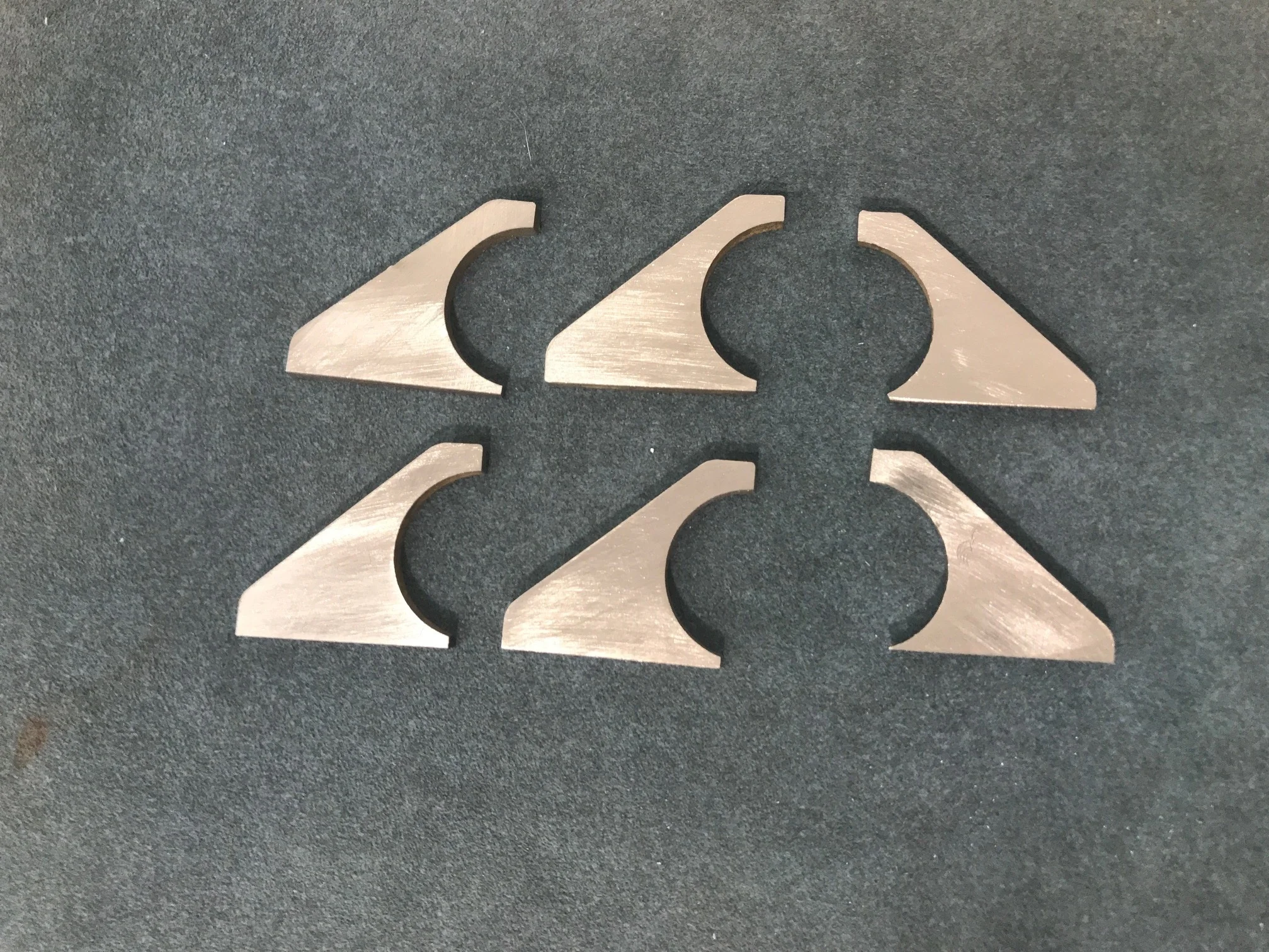
The sway bar’s pillow blocks are mounted to 3/16” steel plates supported by three 1/8” gussets. The Wazer was really useful cutting out the gussets. They’re small and would have been a pain to make by hand. The center gussets are 3/32” shorter than than the end gussets. As you can see if the pictures below, the pre-welding fitment was perfect — just like all of my tube notches LOL. The tube collar’s OD was taller than the pillow block’s offset and they were biding on the steel mounting plate. A 1/8” thick aluminum spacer solved that issue.

Nose Box 1.1 and Oil Filler

The SL-C’s aluminum semi-monocoque chassis is a work of art, but the nose support structure is an after thought. There are two vertical 0.19” aluminum supports, each bolted to the chassis with two 1/4” bolts which are vertically separated by only 2”. It works, but it allows the nose to move around more than one would want and it would absorb very little energy before before a front impact reached the monocoque.

Speed has never killed anyone, suddenly becoming stationary… that’s what gets you.

— Jeremy Clarkson

That’s why modern cars have crumple zones to absorb the energy from an impact during a collision by controlled deformation. While I’m not capable of designing and building an engineered crumple zone, I’m going to build a tube structure which will absorb some energy before the the stout monocoque is reached. I have the following objectives:

  • Stiffen the nose and splitter

  • Absorb some energy in a collision without being too stiff

  • Provide a towing/recovery point at the front of the car

  • Provide a solid mounting plate for the nose hinge

  • Isolate the radiator which is wedged between the support verticals which move around

  • Provide additional support for the intercooler’s two heat exchangers mounted on the splitter

The first challenge was that the floor of the nose was sloped down towards the front-left side because the bottom of the extended foot box was not properly fixed when it was welded. As can be seen in the picture below the footbox extension is pushing the floor down. This required a massive amount of grinding (see the green arrow pointing to the black sharpie line), but I was able to get it to a good place without causing a structural problem.

Each side of tube structure will be mounted to the nose box via two 3/16” steel plates, each with four 1/4” bolts. This results in 4x the bolts and slightly more than 4x the vertical separation between the top and bottom mounting points vs. the stock solution. The top plates ties into the 1/2” upper-control-arm bolts and the lower plate wraps around the corner of the chassis. To create the bend in the lower plate, we clamped the plate and a steel rod which matched the radius on the corner of the monocoque in a vice. We didn’t have an acetylene torch, so we heated the metal with a propane torch. This took a while and the metal never got red. We bent the metal about 30 degrees and noticed that the bend was occurring above the steel rod (i.e., higher than desired). We opened the vice, dropped the hot rod on the floor and re-positioned the bend where it should have been with respect to the steel rod and bent it to ninety degrees… basically a game of hot potato with profanity. The result was a near perfect bend.

The first picture shows the top plate and a modified version of the vertical support mounted on top of the bottom plate. We cut 3/16” off the back of the vertical support to account for the thickness of the lower plate and welded it back together. This allowed us to use the vertical support as a surface on which to mock the tube structure. The stock solution is just the two 1/4” bolts spread 2” apart on the lower plate.

The frame will be made from 1” x 0.095” chrome molly tube. I choose 1” tubing for two reasons; I didn’t want the tube structure to absorb too much energy before crushing (I hope) and there is only about 1” between the vertical support and the radius on the monocoque and I wanted the tube to T-bone the chassis on a flat surface. The picture below shows a mockup of the bend angles using pieces of DOM tubing. The side tube will be made in two pieces.

After bending the side tubes we machined slugs out of 1” solid stock. I learned about the importance of drilling a small hole (i.e. 1/16”) so that hot air can escape the tube while welding. In this case I drilled the holes in the mounting plates. I …

After bending the side tubes we machined slugs out of 1” solid stock. I learned about the importance of drilling a small hole (i.e. 1/16”) so that hot air can escape the tube while welding. In this case I drilled the holes in the mounting plates. I also learned a way to quickly dress up the chrome molly tube. The side tubes are fully welded and tacked to the mounting plates. The tube that crosses in front of the radiator will be 0.095” chrome molly. I now need to decide if I should use 1” or 1-1/4”. I will mount a towing point to the center of the cross bar so strength is important. The 1” tube can be bent and coped into the side supports and it will look at lot better. The only question is, “is it strong enough?”

"Beer Holder" Enigma Solved

The SL-C has two large recesses in the body which are covered when the tail is closed. Lots’s of builders, myself included, ask their purpose. A common response is that they’re for holding a beers. While they’re perfect for that, they’re typically used to hold stuff when working in the engine compartment before the car is painted. Once the car is functional they become unwanted water reservoirs and are usually drilled.

They were originally a place to mount the body to the chassis. The chassis changed, but it wasn’t economical to change the body mold.

In any event, to make room for the cold air induction box located next to the rear vent, I had to mount my oil reservoir near the firewall which would require me to use a long funnel to fill it. What to do?… fabricate a remote oil filler and locate it in the beer holder.

I bought a billet screw-on cap and a -12 AN weld bung. I then used the Wazer to cut an aluminum weld plate, a cork spacer and a carbon fiber trim ring. The spacer was used to pad the cap down so that it was below the surface of the body. Everything was welded on the inside diameter. Welding the outside diameter would have been easier, but I didn’t want oil to get trapped between the weld plate and the weld bung or cap body. The weld bung is offset to make it easier to run a hose from the filler to the tank. The cap fits perfectly inside of the beer holder (i.e., my fingers easily fit between the body and the cap), but I need to increase the OD of the carbon fiber ring to better fill the space and counter sink the flat-head screws. The next step is to modify the top of the oil reservoir, connect it to the filler with some hose and laser etch the cap.

Nose Hinge Group Buy

First batch of 15 hinge sets

Bob and I offered our nose hinge to the SL-C community in what’s know as a “group buy” and so far we have 25 orders. The picture shows the first batch of 15 sets of hinges. That’s 210 billet parts, 75 laser-cut parts and 870 miscellaneous parts.

We made a couple of design improvements. Most notably, we improved the aesthetics of the ball bearing. In the first iteration we used a nyloc to hold the shoulder bolt in place. In the second iteration we added a washer to hide the ball bearing and then machined a longer shoulder bolt to the perfect length and then tapped it for a button-head screw. The result is a completely streamlined appearance. Version one is priced at $700 and version two is priced at $730.

Transaxle Adapter Plate Mounting Brackets

I was having some fitment issues with the shift cable bracket which led me to notice that the engine was sloped three degrees upwards towards the back. The LS7, transaxle adapter plate and brackets were installed by Superlite, so I never paid much attention. The only way to remove the bracket / adapter plate bolts was with a 1/2" impact gun. All of the plating was stripped off of the grade 8 bolts, aluminum speckles fell on the floor, the holes were "threaded" at an angle and the nice chamfered edges were torn and jagged. Even when the bracket is removed the bolt won't slide through. In fact, I needed to use a socket wrench because it was too tight to spin by hand... I guess there's a reason a tap has channels to evacuate chips when threading a hole. Here's what the hole looks like after removing the factory-installed bolt.

What happens to perfectly machined clearance hole when an impact gun forces a bolt in at an angle

Clearly the engine was installed with the wrong brackets. My plan was to fabricate new brackets, but then I got to thinking… The Ford GT drivetrain has only three mounting points, two for the engine and one for the transaxle and it's my understanding that this is a very common approach for mid-engine cars. Since the rear suspension cross brace provides a rigid location to mount the transaxle, it makes sense to remove the brackets causing the issue. This has the following benefits:

  • The three hard mounting points can be replaced with polyurethane mounts to reduce vibrations.

  • The exhaust is easier to construct because you no longer need to do a 180-degree bend to clear the bracket. Remove the 180 will only improve flow.

There is some debate as to weather the brackets are intended to create a stressed member. To be safe, I’ll fabricate a 1” x 2” chrome molly tube flush with the bottom of the chassis to tie the two vertical billet pieces together. I also plan to machine the two mounting ears off of the adapter plate to increase room for the exhaust.

The next step is figure out how to build the engine and transaxle mounts.