Roller Barrel Selector Mechanism

The Albins ST6-M has a roller barrel selector mechanism which is pretty much the gold standard for gear change mechanisms in motorsports. The following video does a great job demonstrating how it works on EX-Jordan F1 gearbox. The gear change section starts at 5:15.

Advantages

  • Few moving parts.

  • Excellent reliability.

  • Direct linkage between the selector forks provides optimally timed movement of each gear’s dog ring.

  • Simplifies the movement of the shift actuator into linear motion.

  • Ability to withstand loads generated by very fast gear changes .

  • Ability to withstand very aggressive shifting (lots of force on the gear change mechanism).

  • The clutch is only used when moving from neutral to first gear or from neutral to reverse.

Disadvantages

The disadvantages primary stem from the fact that there is no synchronizing mechanism to assist in equalizing the speed of the gears.

  • Greater wear on the gears. Race teams view this as the cost of doing business.

  • Requires greater skill to downshift because the throttle must be bliped to match speed. This isn’t an issue if you have paddle shifters and a Gear Control Unit (GCU) does it for you.

  • Shifts are more abrupt.

Albins ST-6M

I attended the Performance Racing Industry (PRI) show in December and enjoyed walking the floor and hanging out with Mesa, builder of the first SL-C, and Hill McCarty, owner of Agile Automotive. I spent a lot of time looking at, photographing and actuating the sliding pedal box in the AP Racing booth to figure out how it worked. It was a nice design, but it would raise the pedals too high so I wasn’t able to apply their approach to my design for the SL-C. I think the sales guy was convinced that I was going to pay the booth a late-night visit and steal it.

I was tempted to purchase one of the CNC mills in Machinery Row, but NFW would something that big go unnoticed by my better half! I resisted all major purchases until the afternoon of the final day… and WHAM-O a bodacious booth babe caught my eye… slender, curved in all of the right places and lots of billet!

The bodacious booth babe… slender, curved in all of the right places and lots of billet!

The Albins ST6-M was one of those things that I couldn’t unsee. I called Hill to ask him about it and he agreed to meet me at the booth. Apparently he’s had great success running them in several endurance SL-Cs.

After purchasing a ST6-M from Agile, Hill moved to the top of my wife’s shit list and she’s trying to introduce me to some new friends who aren’t into building cars. I sent the deposit just as Covid was beginning to spike outside of China, so I don’t have a good idea as to when mine is going to arrive.

You don’t see sequential transaxles in many street cars because the straight-cut gears whine, they’re not cheap and they often only shift well when aggressively driven, something only an idiot would do on the street with a high-powered SL-C. Hill indicated that, if properly tuned, shifts can be smooth even on the street.

I was concerned about how loud the gear whine would be so I flew down to Maryland to listen to Raver Motorsports’ SL-C running on the dyno. It has a loud race exhaust which would make it difficult to judge how noticeable the gear whine would be on a street car. To address that issue I brought a couple of street mufflers and Hill used V-band clamps to attach them to the tips of the race exhaust. Guess what, the exhaust was still pretty loud ;-)

Smartphone videos never seem to capture the sound properly…

I invited Pnut to the audition and his opinion was that the sound wasn’t nearly as loud as he thought it would be and that it would be “fine” on a street, but that ear plugs might be a good idea for a long drive. He thought we were doing some automotive-buddy-bonding, which we were, but I had a second, unspoken, and nefarious motive which I can summarize in two words — plausible deniability. When my wife goes for the first ride and asks WTF that noise is I will tell her “Pnut suggested that I go to PRI, thought that the Albins would be a good idea and certified that it wouldn’t be too loud”… I think that might move Pnut from #2 on her list to #1.

The Albins has a bunch of benefits:

  • Lightweight — it only weighs 180 pounds which to my understanding is 27 pounds lighter than a Graziano, 87 pounds lighter than a Ricardo and 161 pounds lighter than the C8’s transaxle. Reducing weight in this area helps balance the car. The only worst place to have excess weight would be to bolt something to the duck tail.

  • Lightning fast gear shifts, particularly when actuated by a pneumatic shift servo. The Raver Motorsports SL-C is tuned to shift in 40ms. I’ll have a more mild tune for the street and a similar aggressive tune for the track.

  • Roller Barrel Selector Mechanism which is pretty much the gold standard for motorsport gearbox change mechanisms.

  • Drop gears can be easily changed in less than 10 minutes. Simply jack the rear of the car up to prevent the oil from draining out, remove the 10 nuts on the rear cover plate and swap the gear out. The plate is sealed with an O-ring so there is no messing around with sealants or gaskets.

  • Robust: Albins keeps upping the torque specs, but their current rating is 1,100NM of continuous torque in off-road racing (i.e., extended WOT runs, jumping, etc.). I’m also aware of several 2,000+ HP twin turbo cars in the works, so I don’t expect any issues.

  • Eight large inspection ports enable monitoring of the shifting gears, ring gear, differential and pinion. Each inspection port is held in place with a single screw and is sealed with an O-ring.

  • It can be rebuilt while installed in the car. Everything is splined and easy to remove/install without a press, puller or any special tools. The only exception is the pinion bearing which is an interference fit and requires heating of the housing to remove, but it’s not part of a standard rebuild. 

  • The drive flanges align well with the SL-Cs wheel hubs. This, combined with the narrow case, results in long axles which reduce the angle of the CV joint. The puts less stress on the CV joints compared to the Ricardo and the Graziano, especially the asymmetric right side which is shorter to accommodate the front-wheel driveshaft which isn’t used in the SL-C.

  • Integrated oil pump.

The billet bell housing mounts directly to an LS engine obviating the need for an adapter plate.

IMG_8315.jpg

Albins stocks a range of drop gears, but I’ll start with two, one for the street and one for the track.

Hill had a damaged front case left over from a 130 MPH crash — the SL-C did it’s job and the driver walked away. He sent it to me for fitment purposes and it’s downright skinny compared to the Ricardo. Note that the starter flange is inboard of the hole in the stock adapter plate bracket. This provides a lot more space for the exhaust. While not apparent in the picture, the ST6-M sits further above the bottom of the car than most transaxles which, with proper heat shielding, provides enough clearance for a 3” round X-pipe between the bellhousing and the rear billet cross member. If I were racing the car the combination of the Daily Engineering dry sump pan and the Albins would allow the engine to be dropped about an inch.

It is a bit long and I estimate that it will project about 1/4” past the “SL-C” logo molded into the street tail (I only have the front half of the transaxle, so I won’t know for sure until I get it). This isn’t a big deal for me because I’m completely reshaping that section of the tail.

I’m going with paddle shifters and a pneumatic shift servo. More about that later.

Adjustable Pedal Box — 1.1

I purchased a compact ACME nut from McMaster, but I realized that there was no pressure rating for it on their website so I sent them an email inquiry. Here’s their response…

I spoke with our manufacturer and they do not have a static rating for the 12"-10 bronze Acme nut (95120A111).  If you purchase the item and it doesn't work for your application, you can always return it for full credit.

Let me think about that failure mode… If the nut doesn’t hold up to the braking pressure the brake pedal will slide forward and since I’m strapped into a six-point harness I won’t be able to slide forward to even reach the pedal. This would likely be discovered during a panic stop so I might not be around to return it for credit. Yeah, let’s not try that. Nothing against McMaster, the tech person had no idea of my intended application.

Fortunately, McMaster offers a precision ACME nut with a 1,200 pound dynamic and a 4,000 pound static rating. Given that braking is a static activity insofar as the ACME nut is concerned, that’s an ~8x safety factor. The extra weight, size and cost are worth it.

The lead screw bracket was made from 1/4” right angle and welded 1/8” gussets. The flanged ACME nut (bronze) is mounted so that the flange is in compression when braking. In other words, the screws in the flange only come into play when the pedals are being adjusted towards the driver. Even if they fell out, both braking and forward adjustment would continue to work

Completed bracket. A hex nut was welded to the screw to allow manual adjustment (both are 18-1 stainless steel).

Completed bracket. A hex nut was welded to the screw to allow manual adjustment (both are 18-1 stainless steel).

I mocked the adjustable pedal box with laser-cut plywood and 3D-printed gibs. Note the bracket and ACME screw in the upper right of the pedal plate.

I discovered that my pedal plate wasn’t wide enough to allow the right gib to clear the throttle pedal. This was the third or fourth time that I’ve tweaked the width of the plate. This is easy to do, but I also need to remember to change the dimensions of the bottom plate. As a software guy, hard coding interdependent values in multiple files just feels wrong. I was also getting tired of doing the math on the gib/plate tolerances every time I made a change. Fortunately, SOLIDWORKS provides an easy way to provide global dimensions, variables and equations that can be used across mulitple parts and assemblies. If I change one of the variables everything is automatically updated. This also makes it easy for someone looking at the design to understand the clearance between the gibs and the plates without needing to open up multiple files and do the math.

I’m still trying to figure out the best place to locate the gibs and the hole in the floor. I complied the list of responses which is shown below. Even for drivers of the same height there will be variances due to differences in inseam, seat recline, seat padding, etc. The 5’-11” driver with the 12” position seems to be an outlier. If anyone else sends me measurements, I’ll compile them.


0 Likes

Front Suspension Race Cage Modifications

I was away from the car for a month so I had spent a lot of time designing the adjustable pedal box in CAD. I got to spend some time with the car this past week and the CAD fantasy didn’t fit reality. Specifically, the Front Suspension Race Cage wasn’t were it was supposed to be. I’m sure my initial measurements were correct so the high humidity must have warped the monocoque and cage - LOL.

After an appropriate amount of profanity, I realized that the structure was significantly overbuilt for my needs and that it could be easily modified. However, to do that I needed to remove the interior tub which meant that the body, six-point roll cage and dashboard needed to be removed… and then I realized that the steering column also needed to be removed. So I went from something that looked like a car to the following.

The Front Suspension Race Cage adds a lot of structure. The left and right sides are symmetrical and each has the following connections:

  • Eight 3/8” screws through the floor.

  • Four 3/8” screws through the transverse beam in the top of the monocoque and into the front hoop’s mounting plates.

  • Six 3/8” screws through the monocoque and into the upper control arm and shock absorber brackets. Hex nuts are welded to the plate which means that you don’t need a second person to keep the nut from spinning when removing or installing the brackets.

  • One 5/8” screw through the billet lower control arm bracket.

  • Two screws through the interlocking tube couplers that affix the removable side impact bars.

The horizontal tube in the lower right corner captures the 5/8” screw that mounts the lower control arm in the billet bracket. Note that the standard removable side impact bar option would reduce this piece to just the vertical tube, top/bottom plates and interlocking tube connectors on the left.

The bottom 1-1/2” of the tube and plate were cut in half to provide clearance for the sliding pedal box assembly.

A 1/8” gusset and end cap were welded to the notched section.

While this change reduces the strength of the tube I’m not concerned because the monocoque is already stiff and very few cars have this structure at all. The next step is to mock the sliding pedal box.

CET Finished — Almost

The coolant expansion tank is almost finished. Four aluminum spacers were welded to the side of tank to mount it to the fire wall. They provide a 1/4” gap between the firewall and the tank which mitigates the amount of heat transfer into the cockpit. Like everything else in the car, it’s a tight fit.

Once the tank was temporarily mounted, the bungs were positioned and welded. Like all of the other tanks, female bungs were used so that if a male thread gets damaged it can be easy replaced.

There are no mounting spacers on the bottom of the tank because the rear roll cage hoop has a tube in that location.

The connectors for the coolant level gauge have been added, but the company that I ordered the sight tube from is closed due to Covid. The large -10 fitting on the bottom connects to the electric water pump's inlet. The smaller -4 fitting connects t…

The connectors for the coolant level gauge have been added, but the company that I ordered the sight tube from is closed due to Covid. The large -10 fitting on the bottom connects to the electric water pump's inlet. The smaller -4 fitting connects to the top of the coolant swirl pot.

The two -4 fittings on the top right are for the radiator bleed and the engine steam vent.

Adjustable Pedal Box — 1.0

Main.png

I want an adjustable pedal box for several reasons. Firstly, I can, with 100% confidence, state that I wouldn’t get the pedals located in the right place the first time. By the time I got it right, the floor would likely look like Swiss cheese. Secondly, I hate doing anything in the foot box. It’s like one of those “coolers” that prison guards toss inmates into to punish them. I’ve sent my skinny son in there twice when he was 11 and he refuses to go back in. I also know of at least three builders that have had to replace master cylinders in a finished car — yeah, I’d like to skip that. Thirdly, while I don’t expect to have many people driving my car, my plan is to trailer my car to Agile Automotive before paint and interior to safety check, align and corner balance it. Once that’s done we’ll spend several days, or whatever it takes, at a track with a pro driver and a technician to shake everything out.

Most of the adjustable pedal box designs have rails that can foul your heels and raise the pedals higher than desirable. In addition, they typically have more pedal deflection under hard braking than a properly reinforced and and mounted fixed pedal.

The design objectives are:

  • Safety factor >= 2x; assuming 500 pounds of pressure that’s 1,000 pounds

  • No obstructions in front of the pedals

  • Raise pedals no more than 3/8”

  • 6+ inches of granular adjustment

  • Removal or installation of pedals in < 5 minutes with no spilled fluids

  • Reduce pedal deflection under hard braking

  • Integral (i.e., sliding) heel rest and dead pedal

  • Motor driven with manual backup

  • Provide access to foot box for servicing

I was originally planning on dropping the floor to the same level as the recessed seats. That would have stiffened the chassis, allowed me to use commercially available linear rails and kept the pedals flush with the floor. I figured that the potential of scraping would be less than the recessed seats because it was closer to front axle. Will pointed out that when the suspension compressed things would scrape as evidenced by the wear on the nylocs under his pedals. So out went that design.

Gibs

016 - L Gibs.jpg

I was going to machine some dovetail slides ungil Kurt pointed out that simple gibs would work. Gibs are used to guide and control linear movement in applications where heavy loads are encountered. There is a wide selection of L-shaped, V-shaped and T-shaped gibs available. The picture below is an L-shaped bronze gib with graphite inserts to provide maintenance free lubrication.

Rather than placing the gibs on top of the floor, I decided to hang them in a hole cut in the floor. I did this for three reasons; the floor isn’t flat, the pedals can be removed through the hole and the hole provides access to the inside of the foot box. The latter will be useful for at least the brake/clutch pressure and reservoir connections as well as the steering rack/column interface. It may also prove useful when servicing wiring, the steering column and the EPAS.

Hanging the gibs in a hole rather than mounting them to the floor means that there is no off-the-shelf solution. As can be seen below, each gib is mounted to a 1/4” thick bottom plate with three 5/16”-24 flat head screws. Given that the pedals are mounted with four 5/16” bolts and that most of the braking force will be directed forward along the length of the gib, that number of fasteners seems more than adequate.

Bottom Plate.png

As can be seen below, the gibs are mounted to pieces of 1/8” steel right angle with four 1/4” fasteners. The gussets probably aren’t necessary, but that’s how I roll. The piece on the right is shorter because it is so close to the 2” x 6” center spine that the floor doesn’t require stiffening. In fact, depending on pedal placement the angle on the right side might be replaced with a spacer. The floor has about a ~1/8” wave in it because it warped when the monocoque was welded. When the right angle is fastened to the floor it should both stiffen and straighten the floor. That said, I don’t need to worry about how flat the floor is because the gibs only attach to the pieces of right angle and I can locate the mounting holes as needed.

Mounter Slider.png

Pedal Plate

The pedals are mounted to tapped holes in the 1/4” thick steel pedal plate with four 5/16”-24 screws. The upper and lower edges of the pedal plate (gray) that slide between the gibs (dark green) and the bottom plate (light green) are chamfered to reduce binding. The bottom of the pedal plate is positioned 1/8” above the top of the floor to enable it to slide forward over the floor which hasn’t been removed.

It should be clear that when the bottom plate is removed the pedals simply fall through the hole.

Pedal Plate Chamfered.png

Material

Moly Dry Lube.png

The gibs, bottom plate and pedal plate will be machined from steel. I’m considering using 4140 for the two plates and potentially the gibs. Since they’re sliding pieces I’ll need to plate rather than powder coat them. I’d appreciate some guidance on which steel and which plating.

Kurt recommended moly dry lubricant for the gibs.

Cover plate

A cover plate plate will be fabricated from 0.60” aluminum and will be attached to the underside of the car with four Dzus quarter-turn fasteners. In addition to sealing the hole it prevents the screws that fasten the bottom plate to the gibs from backing all of the way out.


acme Screw

I spent a lot of time looking for a linear actuator, but everything that I found with a 1,000 pound static rating was large and heavy. Part of the issue is that actuators with that high of a static rating also have a high dynamic rating with requires a large motor, gear box, etc. This situation requires a very low dynamic rating, just enough to handle the weight of the pedal box and overcome the sliding friction in the gibs.

The best approach was to use a 1/2”-10 stainless steel ACME screw. It provides enough strength and moves a surprising 0.1” per revolution. McMaster sells a hex head lead screw which allows it to be turned with a ratchet or impact wrench. However it was only 6” long which would only provide ~4” of adjustment. I spent a lot of time looking for a longer version until it occurred to me that I could just weld a hex ACME nut to the end — duh!

ACME Screw.png

ACME Screw MOUNTING Bracket

Lead Screw Bracket.png

The lead screw bracket transmits the pedal plate’s longitudinal force into a flanged ACME nut which transmits it to the ACME screw. Since this is the vast majority of the braking force the ACME nut and bracket need a 1,000 pound static rating. The bracket is fabricated from 1/4” right angle steel with 1/8” welded gussets. It’s mounted with four 5/16-24” by 1/2” grade 8 screws which go into threads tapped into the 1/4” pedal plate.

ACME SCREW RETENTION BRACKET

ACME SCREW RETENTION BRACKET.png

The ACME screw dissipates all of it’s force into a 1/4” steel plate mounted to the face of the extended foot box. The collar takes zero braking force and only comes into play when then pedals are being moved forward. Without the collar and the retention bracket the ACME screw would have nothing to pull against when sliding the pedal box forward. Thus the collar and bracket only see a nominal amount of force when the pedals are being slid forward.

Note that the bracket is slotted. This allows the ACME screw to be disengage while the bracket remains bolted to the foot box. The design will change when I figure out how to motorize things.

Range of motion

The following diagrams show the pedal box with 6” range of motion. The range is primarily limited to where the gibs are mounted and how far the pedal can safely project in front the gibs. I need to finalize the location of the floor hole and gibs (more about that at the end of the post), but this should give you a good idea.

heel rest and dead pedal

A heel rest is important given the seating position and that the pedals are floor mounted. I’m also going to incorporate a dead pedal. The twist is that they both need to move with the pedals. The dead pedal shown below is a little small… I need to check clearance with the billet lower control arm bracket and the side impact bar tubing to see what’s possible. The dead pedal would need to be removed before dropping the pedals through the floor (or you could pull the pedals from inside the car).

Dead Pedal.png

MOtor

While the hex nut at the end of the lead screw makes it easy to adjust the pedals with a impact gun or a ratchet wrench, it would be nice to motorize the assembly. The challenge is trying to figure out the smallest motor and gear combination that have enough torque to move the pedal box. It shouldn’t be much, but I’m not sure how much binding there will be between the gibs and the two plates. More research is required.


Connections

The reservoir and pressure lines for the clutch, front and rear brakes will be connected with Staubli quick disconnects. They have a lot of options, so I need to mock everything up to figure out which ones to use. Each connector half will be labeled and each male/female pair will have a different color to reduce the chance to of crossing lines. Nothing like swapping the front and rear brake lines to invert your brake bias!

Deutsch connectors will be used for the throttle position sensor and the motor.

Pedal Box Removal

The pedal box should be able to be removed or reinstalled in 5 minutes. Here are the removal steps:

  • Raise car on lift

  • Turn 4 Dzus fasteners to remove the cover panel

  • Remove 6 bolts and bottom plate

  • Push front of pedal plate up in the foot box up to disengage lead screw and motor shaft and drop the pedals through hole in floor

  • Disconnect 6 fluid lines for the brake/clutch pressure and reservoir lines. Plan is to use Staubli clean-break connectors.

  • Disconnect two Deutsch electrical connectors; one for the pedal position sensor and the other for the motor

  • Pedal box can be placed on bench and the opening in the floor is unobstructed

Next Steps

Mock everything up. I’ll 3D print the gibs and the lead screw bracket and laser cut the plates from plywood. I then need to figure out where the pedal range should be positioned. To that end, it would be extremely useful to know where other builders have placed their pedals. I appreciate it some other builders would send me the following measurements:

  • Type of foot box (standard or extended)

  • Distance A if you have standard or B if extended

  • Driver height

  • Distance C

Measurements.png

Plating

Most steel parts provided by Superlite are either powder coated or zinc plated. However, the following parts aren’t coated and they quickly begin to pit even when kept in a climate controlled garage:

  • Ball joint plates (4x)

  • Lower shock pins (4x)

  • Rear suspension pushrods (2x)

  • Toe links (2x)

  • Rear suspension k-brace support rods (2x)

I’ve have also fabricated a bunch of brackets, backer plates, rocker support arms and other parts that need rust protection. Powder coating works great in many applications, but it chips too easily in areas where wrenching is done (e.g., pushrods, shock pins, shock brackets, etc.). In addition, even when applied with electrostatic spray it’s typically 3-5 mils thick which can conceal cracks during a visual inspection or increase a critical dimension (e.g., shock pins).

Cadmium was the premium automotive corrosion protection, but it’s highly toxic and illegal in most states. After doing some research it seams that zinc-nickel is the premium replacement for cadmium. When compared to zinc, zinc-nickel offers ~4x better corrosion protection and is ~2x harder.

Zinc-nickel is comparatively new and not nearly as common as zinc, nickel, chrome, etc. I called over 20 places and they all had large minimums. One place had a one ton minimum, really? I was about to give up when I found Sav-on Plating who provides a variety of high-volume plating services to the aerospace, healthcare and automotive industries. However, they have a reasonable $250 minimum charge for 5-micron zinc-nickel plating. While their zinc plating is done via racks their zinc-nickel is done via barrels so size is limited. That said, all of my parts fit in the barrel and the minimum would have covered about twice the volume that I sent.

One concern with most plating is hydrogen embrittlement. Apparently, steel with an ultimate tensile strength of less than 1,000 MPa (~145,000 psi) or a hardness of less than 32 HRC (hydrogen assisted cracking) is not generally considered susceptible to hydrogen embrittlement. The hardest parts that I’m plating are non-heat treated 4130 alloy steel which has an ultimate tensile strength of 670 MPa (97,200 psi). That said I had the parts baked for 14 hours at 400° F per the table above just to be safe. That cost an additional $50.

Hydrogen Emnrittlement.png

I also decided to have a passivization and clear layer applied which added another $50. Apparently the passivization layer can discolor the finish a bit, so if you want a brighter more consistent finish I’d skip the passivization.

Most of the car has a machined or brushed aluminum finish so I didn’t want a polished finish. I removed the pitting and rust with a combination of a belt sander, a Dremel with an abrasive wheel and a tube polisher with a surface finishing belt. The only parts that I did polish where the shock pins because I wanted to ensure that they’d glide easily into the shock’s monoballs.

plating 1.png


Air Jack Manifold

Abe and I fabricated the mounts for the air jack system earlier last year (details here) and I finally got around to making a manifold to split the air to the three jacks. Some cars on air jacks go up and down in an awkward manner which I assume is due to a combination of variances in weight distribution and restrictions in the lines. Since I have one jack up front and two in the rear I wanted a way to tune things.

I looked into using valves, but everything that I found that was rated for 30 bar (435 psi) was larger and heavier than I wanted. So I decided to go old school and thread a hex plug in front of each AN adapter. By drilling different size holes in the plugs, I can change the level of restriction going to each line allowing me to tweak how the car is raised and lowered… at least that’s my theory.

The system runs on -6 AN lines and fittings so I started looking for the smallest hex plug with a hex key that would accommodate a 3/8” hole. I spent a lot of time looking at imperial fittings, but just about everything that I found had tapered threads which was a nonstarter. Most metric plugs and fittings seem to have parallel threads and I was able to find a M20-1.5 stainless steel hex plug and an -6 AN to M20-1.5 adapter. The only standard hex plug that I could find cost $32 which was unreasonable, but I found one with a flange for under $10. So I bought several and cut the flange off. This doesn’t leave a lot of material for the hex to wrench to grab, but it also results in a shorter plug which is advantageous. Once the flange was removed I dropped a 3/8” end mill through the middle.

After I had machined everything, I realized that since I tapped the holes all of the the way through the plug had nothing to bind against and might unwind into the manifold’s inner chamber. In addition, machining the plugs to tweak the amount of restriction was a PITA, so I decided to Loctite the plugs in place and cut a restictor disk from 0.90” stainless.

From left to right, AN adapters, copper crush washers, restrictor disks, modified hex plugs and an unmodified hex plug.

From left to right, AN adapters, copper crush washers, restrictor disks, modified hex plugs and an unmodified hex plug.

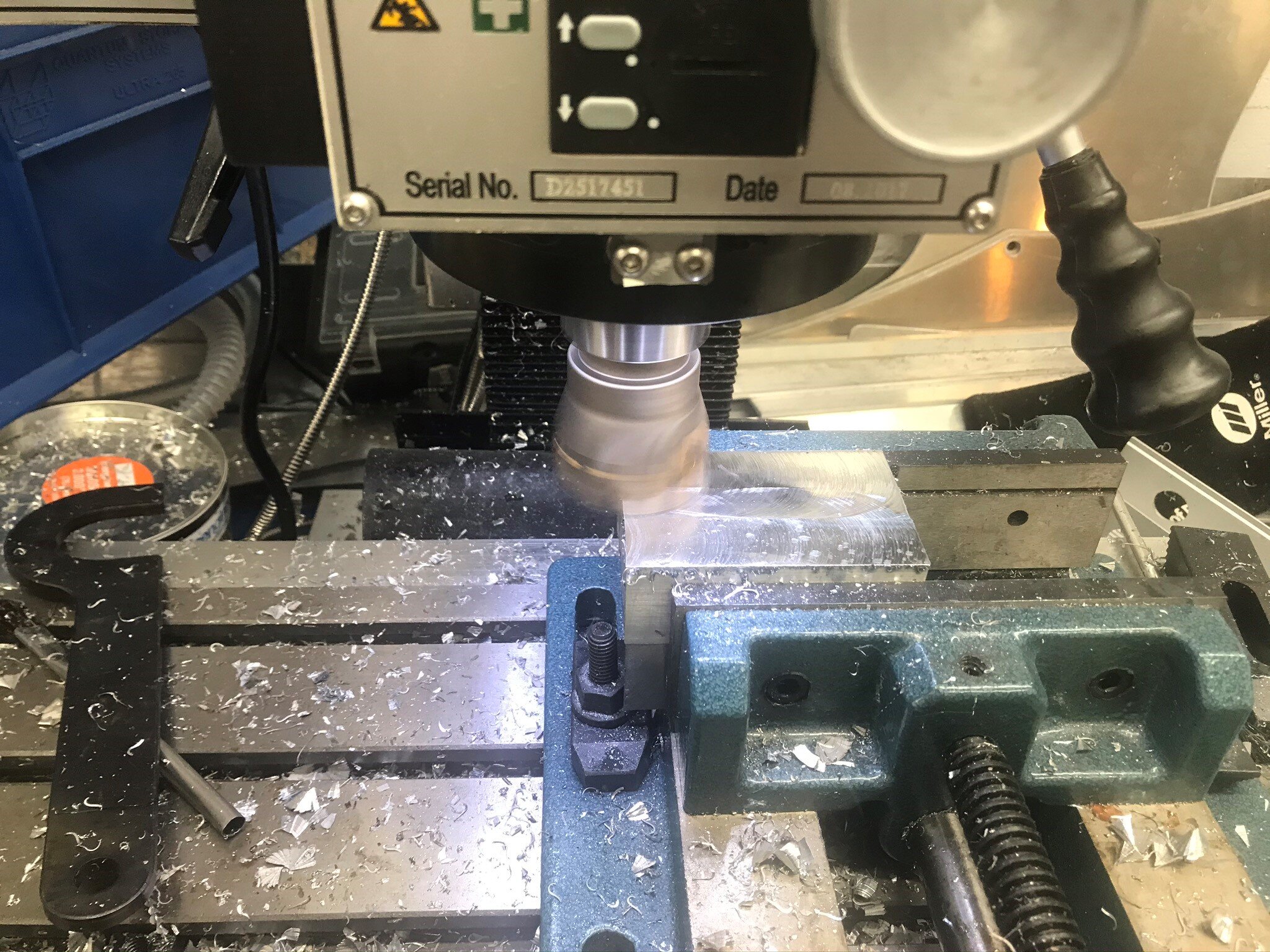
The manifold started as a hunk of aluminum. After cutting it to length I face milled all six sides to square things up. I ordered a 18.5 mm drill bit and when it arrived I realized that it was too big for the 1/2” chuck that I have in the mill. Same problem with the drill press). D’OH!

Facing all six sides

Facing all six sides

Fortunately they make drill bits with reduced shanks. So I ordered one and when I tried to chuck it up I realized that I didn’t have enough Z-axis — Double D’OH!

The issue is that the drill chuck has an integrated collet and it protrudes 3.4” lower than a plain collet does. After an appropriate amount of profanity, it occurred to me that the bit’s reduced shank was 1/2” and I had a 1/2” collet. I had never considered using a collet to hold a drill bit — duh, problem solved.

Given that the adapter uses a crush washer to seal, it’s important that the manifold’s surface is flat and that the hole is tapped perpendicular to the surface. The facing step mentioned above met the first condition, but I’m not great at tapping perfectly straight holes by hand so I often use a tapping block. For critical threads like these ones I have mounted a tap in a drill press, applied pressure on the quill handle and spun the chuck. That works, but it’s awkward. I then discovered that larger taps have an indent, called a center hole, in the top which is used to receive a tap guide. For under $20 I purchased an adjustable spring-tensioned tap guide.

From left to right; reduced shank drill bit, tap with center hole, spring-tensioned tap guide and tap handle.

To drill and tap a perfectly straight hole I do the following:

  • drill the hole

  • swap the drill bit with a counter sink

  • bevel the hole

  • swap the counter sink with the tap guide

  • insert the tap into a tap handle and place it in the hole

  • add cutting fluid

  • drop the quill ensuring that the point of the tap guide is centered in the hole in the top of the tap

  • continue to drop the quill until the spring is compressed

  • lock the quill

  • tap as normal

This ensures that the tap is perfectly centered and vertical. This is significantly easier than inserting the tap directly into the chuck because you don’t need to worry about applying constant pressure on the quill (the spring automatically does this) and you can use a tap handle rather than the chuck to rotate the tap.

IMG_0931.jpg

I arranged the three outlets in a “T”. To keep things balanced, the outlets for the rear jacks symmetrically exit the sides and the outlet for the front jack exits the bottom. I was originally going to tap the inlet, but I didn’t have as much material as I had planned so I had Abe weld a bung. As shown below, the air jack connector mounts directly to the manifold.

AirJack 1.jpg

The next step is to finish the plumbing and test the system. I ordered a nitrogen set up from Paoli in Italy several months ago. It seems that they have the pandemic under better control, so I’m hopeful that the equipment will show up soon.

Brake Duct Openings

I’m working with Andrew from Aeroworks Performance to fabricate some body parts. He has extensive experience using 3D printing to create composite aero parts. Depending on the situation he either prints a female mold, a male buck or the actual part. He built a 3D printer with a 27” L x 13” W x 14” H print size and he’s planning one that’s capable of printing a splitter as a single piece. For now, he glues pieces together.

I want my first rodeo to be a small one so first up are the brake ducts and radiator outlet. The primary reason for enlarging the brake duct openings is to increase airflow to heat exchangers located on the left and right of the radiator while also feeding a brake duct. I also think that the modification improves the look of the car.

Kevin designed two shapes, angled and rounded, each with a narrow and wide variant. The narrow angled version (A1) is the same as what Allan has done on a bunch of cars. I’m still in negotiations with his licensing department, but so far he’s a tougher negotiator than Mesa… LOL.

IMO the angled versions are more aggressive and modern. The rounded version is less aggressive and more in keeping with the the curves found elsewhere on the car. Thoughts?

Front-details-Angled-S3D.jpg
Front-details-Angled-wide-S3D.jpg
Front-details-rounded-S3D.jpg
Front-details-rounded-wide-S3D.jpg

Expansion Coolant Tank

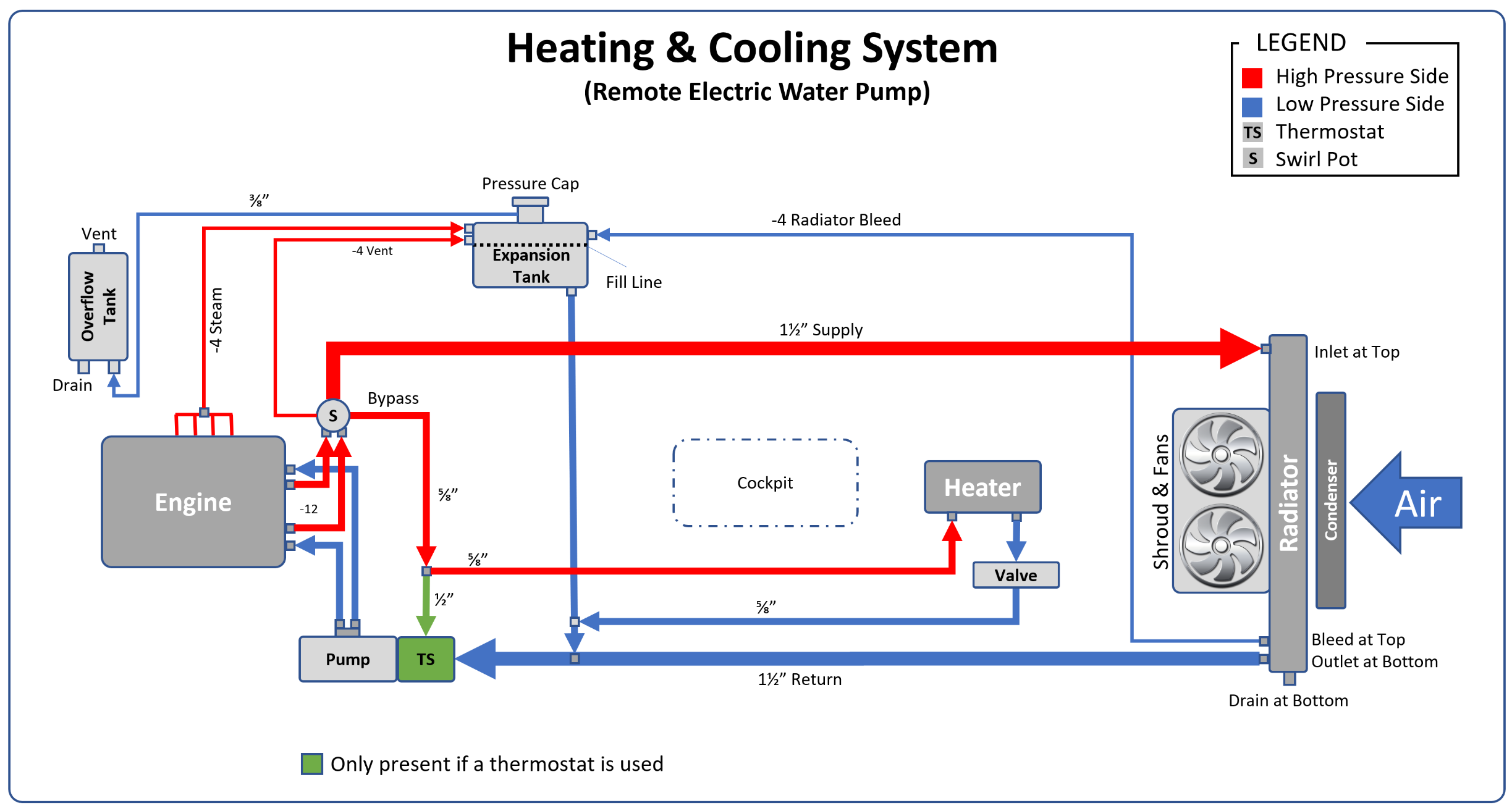
Heating&CoolingSystem.png

One of the many challenges with a mid-engine car is bleeding and then keeping air out of the cooling system. This is critical because as the amount of air increases there is an exponential loss of heat transfer efficiency; 2% air results in a 8% loss of efficiency and 4% air results in a whopping 38% loss!

Cooling systems are pressurized because higher pressure results in a higher boiling point. For example, water boils at 212° F, but at 20 psi it doesn’t boil until 259° F. This is a good thing because GM’s LS engine management doesn’t kick on the cooling fans until 220° F. High-performance cars run at 22-24 psi, racing cars run at 29-31 psi, and Formula 1 cars run as high as 50 psi.

A pressure cap provides the cooling system with a relief valve. Without it, pressure might build until something burst. The pressure cap is placed at the highest point in the cooling system to collect air bubbles and steam. If the pressure exceeds the cap’s rated threshold, the cap opens to relieve the pressure. On most cars the radiator is higher than the engine and the pressure cap is built into the top of the radiator. This is so common that the pressure cap is often referred to as the radiator cap.

However, the SL-C is really low and the top of the radiator is below my knee… and I’m not tall. For this reason, the pressure cap must be relocated elsewhere. The solution is a coolant expansion tank which serves two purposes. Firstly, it allows the pressure cap to be relocated from the radiator to the highest point in the cooling system (in my case as high as possible on firewall in the engine compartment). Secondly, it serves as a deaeration chamber, which continually separates air bubbles and steam from the coolant.

The expansion tank is known by many names (e.g., surge tank, recirculation tank, coolant expansion fill tank, deaeration tank, etc.) and it is often confused with the overflow tank which serves a completely different purpose. The expansion tank is pressurized (it has a pressure cap) and when the pressure rating is exceed the cap opens and it releases the steam that has collected underneath it. Once all of the steam has been purged it may release some coolant. Many street cars allow released coolant to overflow onto the road, but that approach won’t pass tech inspection at most tracks for obvious reasons.

To address this hazard, an overflow tank is used to capture any coolant that’s released by the pressure cap. The overflow tank isn’t pressurized — otherwise it would need a pressure cap which would need to overflow to another tank which would accomplish nothing. The hose from the expansion tank is usually plumbed into the bottom of the overflow tank so that when the car cools and the coolant contracts the overflowed coolant is drawn back into the system.

Second-Gen Tank

I copied a tank that was designed by some early builders (Mesa, Howard and Will) and I made the following changes:

  • The engine steam and radiator bleed connections were moved from the bottom to the top of the tank to improve deaeration (i.e., air bubbles and steam don't need to percolate through the liquid).

  • The mounting flange was replaced by four aluminum spacers that provide a 1/4” air gap between the tank and the firewall to reduce heat transfer into the cockpit. To accommodate this, the tank is 1/4” thinner.

  • A sight tube was added.

  • The hose barbs were replaced with female ORB weld bungs. This allows a wide range of fittings to be used (e.g., AN fittings, hose barb, etc.) which means that I can change my mind on how things are plumbed.

  • A bung was added to the bottom of thank for the swirl pot bleed line.

  • The aluminum thickness was increased from 0.093" 5052 aluminum to 0.125". A little thicker than necessary, but I never wanted to have an issue.

  • A baffle was added to reduce coolant sloshing. This, combined with the thicker aluminum, will prevent the rear from bulging when pressurized as observed by several owners of the gen-1 tanks.

I modeled the tank using the sheet metal features in SOLIDWORKS. The aluminum pieces were designed to have a 50% (i.e., 0.0625”) overlap to provide perfect corner weld joint. It looks good in CAD, but time will tell if it comes out as planned ;-)

Coolant Expansion Tank 1.png
Coolant Expansion Tank 3.png
Coolant Expansion Tank 2.png

It took a little while for me to figure out the sheet metal features, but that effort was rewarded because SOLIDWORKS generates the flat patterns and bend lines to form the shape. This takes into account the type and thickness of the material, the bend angle, roll radius, etc. The image below shows the shape and three bend lines to form the top.

Boston Clam Bake

Clams.jpg

The back ordered clamshell couplers and ferrules arrived and Abe was able to get most of them welded, but I’m still waiting on the XRP PROPlus hose and crimp collars.

The swirl pot is finished. The two -12 inlets on the top left connect to flex hose, the -24 outlet on the bottom right connects directly to the 1-1/2” stainless steel tube that runs down the side pod and the two threaded bungs on the middle left attach to a chassis bracket.

IMG_0833.jpg

The radiator inlet and outlet are connected to the 1-1/2” stainless steel tubes via -24 hose and clamshell connectors.

Right side, the radiator weld ferrule is just tacked

Right side, the radiator weld ferrule is just tacked

Left Side

Left Side

1-1/2” stainless steel tube, weld ferrule, clamshell coupler and hose end

1-1/2” stainless steel tube, weld ferrule, clamshell coupler and hose end

The next step is to finish the welding the tubes in the engine compartment and fabricate the flex lines once the parts arrive.

C7 180-Degree Crossover

I’ve been doing some additional research on 180-crossover exhausts, specifically on LS engines. While the C7 video in the last post has an LT and I have a LS7 my engine is a custom build and supercharged like the LT, so it hopefully provides some insight into what mine might sound like. In any event, that car has a build thread and I was able to determine how it was fabricated. As I previously mentioned, the optimal approach for scavenging and sound is a round collector with the tubes firing in a sequential clockwise or counterclockwise manner. As can be seen in the picture below the fabrication is top notch and flat collectors were used for fitment reasons.

ciiTlLC.jpg

I was curious if the fabricator was able to optimally sequence both collectors. As can be seen below, the top collector is as good as you can get with a flat shape, but scavenging/sound won’t be optimal between B and C. The bottom collector has two discontinuities; B-C and D-A. Does it matter? Probably very little, but a round optimally-sequenced collector would likely sound a little more refined.

C7 Flat Collector.png

Here’s another video of that car. The first 30 seconds has an x pipe and the following 30 seconds has no merging after the collectors. The owner preferred the version without the x pipe so that part of the exhaust went in the recycle bin. Interestingly, Abe fabricated and installed an x pipe in a Ferrari 812 Superfast last week and everyone preferred that sound.

The following picture shows the version with the x -pipe.

026ke8R.jpg

Here are a couple of other video/sound clips. All of the cars are white and I’m fairly sure they’re all the same car. I don’t think the first video has an x-pipe and the last two definitely don’t have one. In any event, they provide some inspiration.

180-Degree Crossover Exhaust

There’s nothing wrong with the grumble of an American V8. I have a cobra with a 427 side-oiler, Webber carbs and side pipes. It sounds bad ass and I love it, but I want to do something a little different for the SL-C. I considered doing a 180-degree crossover exhaust, but there is no room to do it unless I cut through the top of the body which I don’t want to do. So, I was planning on a simple exhaust using the OEM exhaust manifolds because, according to my engine builder, custom headers may look cool, but they won’t generate any more power and will only lead to heat, fitment and leaking issues.

However, I keep looking at the 2-3/8” between the Daily dry sump and the bottom of the car. I considered lowering the engine to lower the center of gravity, but the supercharger snout and induction tube would hit the 2” x 6” chassis tube. If this were a pure race car, I’d notch the chassis and lower the engine, but for my use case that doesn’t make sense. It occurred to me that the space under the oil pan could be used for a 180-degree crossover exhaust.

So, what’s a 180-degree crossover exhaust? To understand that you need to first understand the high-level differences between a cross-plane and flat-plane engine. A cross-plane crank has journals separated by 90 degrees and a flat-plane crank has journals separated by 180 degrees. When viewed along the axis of rotation a cross-plane crank looks like a cross (i.e., “+”) and a flat-plane crank appears flat (see image below). If you think about it, if two lines are 180-degrees apart they are parallel and will appear flat when the plane that intersects them is viewed on its edge.

The following table summarizes the high-level pros and cons of each approach.

With the exception of the recent Mustang Shelby GT350, all American V8s have a cross-plane crank and many “exotic” cars (e.g., F1, Ferrari, Lamborghini, McLaren, etc.) have flat-plane cranks. There has recently been a lot of hype that cross-plane engines are exotic. This is a pile of bull you know what.

Firstly, a cross-plane crank can only be used on an engine with a number of cylinders divisible by eight, which for cars means 8 or 16 cylinders. Secondly, flat-plane cranks are used in everything from Honda Civics to mail trucks. This article does a great job discussing the nuances between cross and flat-plane engines and the origin of the recent hype.

OK, back to the exhaust… Flat-plane cranks optimize the intake and exhaust processes by alternating pulses between the the left and right sides of the engine — L-R-L-R-L-R… These even pulses, when combined with a high-revving valve train, are what gives Ferrari’s and Lamborghini’s their “exotic” sound.

A cross-plane crank doesn’t alternate pulses between the left and right sides. It has a R-R and L-L in the middle of the firing sequence which is what creates the “American” rumble. This also creates a crowded condition in the collector because two exhaust pulses, separated by only 90 crank degrees, are flowing through the collector. This requires a larger collector and reduces scavenging, both of which have a negative effect on power.

Enter the 180-degree crossover exhaust. Rather than plumbing all the tubes from each side into the same 4-1 collector, two of the tubes from each side are crossed to the other collector to create evenly spaced exhaust pulses — just like a flat-plane engine. This produces a broad power band (i.e., smaller collector), increases scavenging and results in a sound with less rumble, at least at mid to high RPMs.

The original GT40s, including the ones that won Le Mans in the 60’s, had 180-degree crossover exhausts. The picture below is of an original GT40. You can see why the exhaust is commonly referred to as a “bundle of snakes.” Most headers are made by sectioning fixed-radius, mandrel-bent U’s and welding them together. If you look at the graceful curves on the headers below, it’s clear that they weren’t made that way. I’m not sure how they did it, but it took some serious skills.

Ford_GT40_MKI_1967_004.jpg

Yeah, I realize that a crossover exhaust will be a lot of work, create potential leaks and create heat issues, but if it were easy everyone would do it. While the original bundle of snakes increased power my fitment constraints may cost me some power (e.g., longer and skinnier primaries, increased number of bends, etc.), but I have excessive power so that’s not a concern. So why am I going to try and do it? For the sound. The sound of the Vette in the following video is bliss… please ignore the irresponsible driving.

Round vs. Flat Collectors.png

That car has an LS7 with equal-length 36” long primaries. For fitment reasons the primaries are 1-3/4” and the collectors are flat. Round collectors, particularly when the primaries are sequenced to fire in a circular pattern (clockwise or counterclockwise), offer superior performance due to improved scavenging.

I conceptually understood that two of the primaries from each side had to be crossed over, but how a double pulse on each side occurred and how the tubes were routed wasn’t intuitive to me. To get my brain wrapped around things I put together the following diagram which illustrates the exhaust pulses down the left and right cylinder banks for eleven compression strokes:

Note that the stock exhaust creates a double pulse in each cylinder bank; the right during compression strokes 4 and 5 and the left during compression strokes 8 and 9. The 180-degree crossover exhaust crosses these primaries to the opposite side which creates a symmetrical pulse down the left and right cylinder banks.

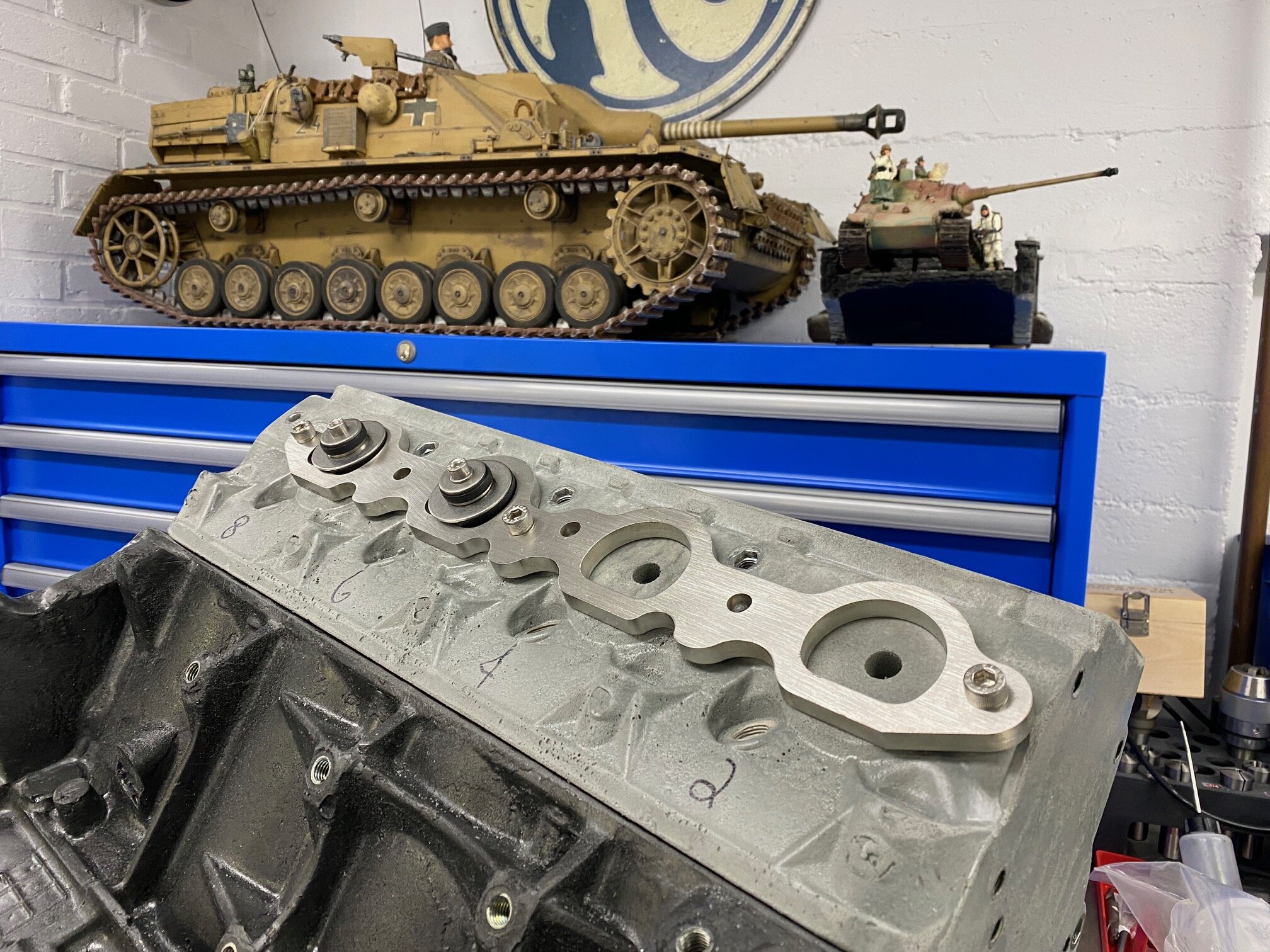
What do you buy for an 8-year old when a pandemic is looming? LEGOs of course. What do you buy a 50ish-year-old boy? Big-boy LEGOs. Specifically, a plastic LS7 engine block and an 1-7/8” icengineworks set to mock headers.

The plastic blocks are attached to the exhaust flange using a block starter / tube adapter which are composed of pieces of rubber sandwiched between stainless steel disks. When the screw is tightened the rubber is compressed causing it to bulge. The large piece of rubber grips the inside of the exhaust tube and the small piece of rubber grips the plastic block.

I didn’t have short starter tubes tacked to the exhaust flange as suggested by the instructions so I tried to insert the block starters directly into the exhaust manifold. That didn’t work because the exhaust ports are D shaped and the starter blocks are round. A little grinding was all that was required to get everything to fit. From left to right; front of starter block, rear of starter block, and disassembled starter block with modified front and rubber disks.

IMG_0474.jpg

I had to drill a relief hole in the middle of exhaust port to accommodate the nutsert and screw on the backside of the tube starter. I subsequently realized that I had the flanges mounted upside down ;-)

IMG_0479.jpg

I’m not sure if I’ll be able get it to work out the way that I want, but it gives me something to do during the pandemic!

We Don't Need No Stinking C7 Hubs

In response to my last post I was asked the following on the GT40's forum:

I would have thought they would have gone directly to the C7 hub and 33 spline stub axle. Cheaper hub ($90) but still a X Tracker and with the larger/stronger 33 spline strength.

I don’t know what drove Superlite’s decision, but the dynamics of their procurement process is obviously different than ours and you would also need to take into account the pricing and availability of the larger-spline-count stub axle.

I’ve been talking with Hill McCarty at Agile Automotive about a new transaxle and during that process we discussed hubs. Long ago they had made modifications to support the latest version of the C6 ZR1 wheel bearings. Although they have never had any play in the bearings they age them out every two years. So that’s about 10 events per year, several of which are 24+ hours with the car pulling 2 lateral g’s. That’s a lot more abuse than my car will ever see — well, other than some launches :-)

Hill did point out that heat needs to be properly manged. While the aluminum upright does a pretty good job of wicking away heat so long as there is air flow, you need proper brake ducting if you’re pushing the car that hard.

With top-end C6 hubs the weak link is probably the CV joints. This is particularly true if you have a Graziano because the 4WD design, which is useless for a SL-C (at least so far), has asymmetric axles with the right axle being a good bit shorter. This puts more strain on the right-side CV joints.

Rear Upright and Hub Upgrade

Some of the SL-C builders who are tracking their cars were blowing out their rear bearings. The stock C4 bearings and 27-spline stub axles are OK for street use, but they are not suitable for a SL-C on racing slicks (forum discussion here). While Superlite offers a racing upgrade for the suspension it’s not suitable for the street. In mid 2019 Superlite began shipping cars with new uprights, C5/C6 bearings and 30-spline stub axles. In addition to being more robust, the new hubs have integral reluctors which are an improvement over the reluctor rings that I had previously installed on the CV joints. Specifically, everything is enclosed and there is no need to fabricate custom sensor brackets which might get knocked out of alignment.

Fortunately, Superlite offers an upgrade path for existing cars like mine. The upgrade comes with the following; two uprights, two spacers, six stainless steel dowel pins and two stub axles. Unlike the previous generation uprights which were handed, the new uprights and spacers are symmetrical and can be used on either side. I wasn’t sure what the two 7/16”-14 holes where at the top of the uprights so I called Superlite. Apparently the new upright is the same as the one used on the GT-R which uses cross bolts for the top billet piece. So what might have been four different upright parts, is one. In addition, the use of a spacer allows a thinner piece of aluminum to be used for the upright which reduces material costs and machining time. This was a smart change.

The pictures below compare the older right rear upright (on left, part# SLC-RR-UR-01R) to the new upright (on right, part# SL-RR-UR-02RL).

Right rear uprights as viewed from inside the chassis; old on left, new on right. The front of the car is to the left.

Right rear uprights as viewed from the wheel; old on left, new on right. The front of the car is to the right. Note that the new upright has the spacer mounted using dowels in the three smaller holes.

Right rear uprights as viewed from the front edge; old on left, new on right. The 1/2” thick spacer is mounted to the new upright which makes the new assemble ~0.2 thicker than the old version. I had drilled and tapped holes for the parking brake br…

Right rear uprights as viewed from the front edge; old on left, new on right. The 1/2” thick spacer is mounted to the new upright which makes the new assemble ~0.2 thicker than the old version. I had drilled and tapped holes for the parking brake bracket when this picture was taken.

Superlite forgot to send me the dowels, so I ordered some from McMaster (part# 90145A541). The first step is to insert the dowels into the uprights (light taps are all that’s needed). As mentioned above, the uprights are symmetrical so you need to insert the dowels into the side that faces the hub/tire. Once that’s done, the uprights are handed. The spacer can then be placed over the dowels and lightly tapped until it’s flush with the upright.

Another benefit to the new version is that it’s easier to drill and tap holes for the parking brake brackets. As can be seen in the pictures above, there is significantly less pocketing in that area than the old version and the middle web is ~0.91” (~23 mm) thick which easily accommodates M10 screws. I used the DRO on the mill to drill the holes, but I used layout dye and a micrometer to prevent another D’oh. Measure five times, drill and tap once. Following the 2x thread diameter rule of thumb for aluminum I drilled the holes 25 mm deep and used a M10-1.5 bottoming tap.

I bought SKF Corvette Racing Hubs from TPS Motorsports with pre-installed ARP studs. According to their website:

The SKF Corvette Racing Hub unit is designed to provide high stiffness during cornering, thereby reducing piston knock-back and the need to tap the brakes (confidence tap). It has <10 micron run-out and is designed for durability and to maintain preload at sustained loads of 1.2g!

Six M12 - 1.75 mm thread x 75 mm Socket Head Cap Screws and six M12 washers are needed to mount the hubs to the uprights. I’m not sure what comes in the new kits, but McMaster only had that length in iron oxide so I spent a bunch of time looking for zinc-plated ones. The smallest quantity I found was a box of 80, so if anyone wants some PM me and I’ll ship six to you at cost.

I drilled the socket head cap screws so that I can add safety wires when the car is finished. The hub can be clocked in any of three orientations and I positioned it so that the wires would be as close as possible to the parking brake. This keeps them away from the primary brake caliper and enables me to run those wires with the electric parking brake wires. The reluctor wires are very close to the stub axle and there is no provision to keep them in place. I’ll figure out how to affix them once the parking brake brackets are machined.

I wasn’t able to mount the upgraded Brembo GT two-piece rotors to the hubs because the holes machined in the rotor hat by Superlite have a very tight tolerance (a good thing). I assumed that the longer studs were slightly askew so I opened the holes a little. I found that that a 31/64” bit fit the holes perfectly, so I used one to locate each hole on a drill press. After clamping the rotor to the table, I used a 1/2” bit to open the hole and then a counter sink to chamfer the edge. While not a complicated process, I also chamfered the other side so in total that’s 20 hole locating and clamping operations, and 50 bit changes! I was able to get the rotor to fit by tapping it with my hand which caused the threads to create a few shavings. My bit set only goes to 1/2” so I’m going leave things tight for now.

I’m waiting for some parts to be plated (e.g., the ball joint plate, lower shock pins, etc.), so I haven’t mounted the hubs to the car yet, but I’m not expecting any issues.

Note that I didn’t upgrade the front uprights and hubs because, as discussed in a previous post, I had already upgraded the front hubs to re-buildable race hubs which are much nicer than the SKF racing hubs. Unfortunately they are no longer available.

image-asset.jpeg

Holes on a Tangent

IMG_0155.jpg

I was asked how I cut the clean holes on the tangent of the swirl pot. While I do have access to Abe’s tube notcher, this was simple because the holes were drilled at 90 degrees. I used a bi-metal hole saw that I purchased at Home Depot (sharp tools make clean cuts). I dropped a scrap piece of tube into a vice on the mill so that when I dropped the quill it would just miss the end of the tube. This allowed me to see where the saw would plunge and to move the Y-axis until it looked like I had everything lined up perfectly (i.e. the outer edge of the cut was just inside of the ID of the tube at the middle point). I then slid the tube under the hole saw, put some oil on it and cut away… nope, I was off a little so I tweaked the Y-axis and did another test cut…. bingo, it was spot on. 

IMG_0144.jpg

In went the real piece, I aligned the x-axis so that the middle of the saw was aligned with the sharpie mark (see on first hole above) and the hole came out perfect. I moved the X-axis and drilled the second hole. The inside was cleaned up with a deburring tool similar to the one shown below and the outside was cleaned up with the tube finisher discussed in a previous post.

s-l300.jpg

This could have been done almost as easily using a drill press and a drill press vice. I would orient the vice so that the fixed jaw was closest to column, clamp a piece of scrap and eyeball alignment the same way as described above. Since you can’t tweak the X-axis on a drill press, I’d cheat the fixed jaw a little closer to the column so that shims could be used to tweak the position. I keep scraps of every thickness in a box to use as shims when mocking or machining parts. If you don’t have a cache, just order a bunch of small pieces of various thicknesses from McMaster. I’d then clamp the vice to the table, do a test cut, and shim as needed. The only trick would be to not rotate the tube when drilling the second hole.

Coolant Swirl Pot

I’ve been through a bunch of iterations on the cooling system. At this point, I not using any of the heating or cooling parts supplied by Superlite nor the LS7 mechanical pump. During the process the following diagram has been through multiple iterations and hopefully this is the final, final, final version — LOL.

As I’ve previously mentioned, the single best resource that I’ve found on automotive cooling systems is this article on 4x4 Pirates. While it doesn’t mention remote electric pumps or mid-engine cars, its content is directly applicable.

My current plan is to not run a thermostat, but I have ensured that there is space to add one if needed. The LS7’s mechanical pump places the thermostat on the inlet side of the engine for reasons covered in the aforementioned article. While placing it on either side would work, fitment works better for me on the inlet side.

The one feature that I’m going add that isn’t covered in the article is a coolant swirl pot. Apparently these are very common in race cars to separate air bubbles. The Raver SL-C has one and the following excerpt is from Engineer to Win:

I still consider the water system de-aerating swirl pot (as described in PREPARE TO WIN) to an absolute necessity on any racing car... I strongly prefer to make the header tank non-circulating as shown in FIGURE [184']. In this case I run a good sized hose (say, dash 10 or dash 12) to the inlet of the pump simply to facilitate the filling of the system. If, for whatever reason, the header tank is part of the coolant circulating system then the size of this line must be severely restricted (say 1/4" ID) in order to prevent any sizable portion of the coolant from following the path of least resistance from the header tank to the water pump, bypassing the radiator(s) entirely.

—Carroll Smith

Do I need one? No, but I needed to merge the two -12 lines from the engine into the the 1-1/2” tube that runs sown the left side pod and the swirl pot serves that purpose. In addition, continual de-aeration can only help things considering that 2% air in the system results in 8% less heat transfer, but 4% air results in 38% less!

The swirl pot is made from 2-3/4” aluminum tube and I decided to dome the top to promote air bubbles escaping… plus it looks cool;-) I purchased a 4” half sphere and while I was pondering how in hell I was going to clamp it so that I could cut the tip off, Abe tack welded it to a scrap 4” tube which made it easy to cut on a horizontal band saw. Once the cut was cleaned up, I needed to mark the exact center. To accomplish this, I put some layout dye on the middle, stood it on end against a vertical surface, measured the OD on a digital height gauge, divided that number by two, reset the gauge to that number, and rotated the cap while marking it with the foot. Given that all of the lines intersected, I knew that I had the center — or as close as possible given that the OD wasn’t perfect.

IMG_0123.jpg
IMG_0124.jpg

I used a hole saw to cut the bottom and the arbor created a hole in the middle. Rather than fill the hole, I decided to enlarge it and add a bung for a drain. I ground the back side of the weld bungs until they were flush with the inside surface. I’m still waiting for a couple of parts, but it’s almost ready for Abe to weld together.

IMG_0155.jpg

Self Quarantine + Garage = Quality Time

IMG_0436.jpg

My son is interested in cars, but for the most part he’s memorized the specs on all of the exotics. He’s somewhat interested in the SL-C project, but I’ve been careful to not push it on him. One of the good things to come out of sheltering at home is that we’ve had an opportunity to spend some quality time in the garage — what’s better than that?

The battery in my 1993 BMW 850 CSi was dead and my charger couldn’t revive it, so I figured I’d teach my son how to swap the battery. In the end, I learned that the car has two huge batteries in the trunk. To get to the second one, we had to remove the CD changer (the black box above the wrenches). It was the first CAN Bus car and it had two ECUs, one for each cylinder bank — apparently one wasn’t powerful enough to manage 12 cylinders. I guess to power all of the new-fangled electronics it needed two batteries. It’s kinda cool because the car is passing through three generations — James Richard bought it, James Scott is enjoying it and James Connor is being groomed for it LOL

Last week we also went over thread pitches, tapping and drill press basics. He then drilled some holes in scrap, used clecos to keep everything aligned and then riveted them together. Connor thought the clecos and rivet gun were cool. Next week we’re going over milling machine basics — fixturing, edge finding, facing, making slots, using the DRO, etc.

So being stuck at the house isn’t all bad!

A-Pillars

whoopass.png

ALL PICTURES AND ACTIVITIES SHOWN AND DISCUSSED IN THIS POST THAT TRANSPIRED OUTSIDE THE BOUNDS OF MY HOUSE OCCURRED BEFORE I SELF QUARANTINED. Well “self” is a euphemism for my my wife and mother demanding that, given my underlying health conditions, I not leave the house. I’m going stir crazy, but the last thing that I need is those two opening a can of whoop ass because they thought I sneaked to Abe’s shop to have some welding done!

pillars 1.png

The front hoop is constructed from a single piece of 1.5” DOM with a flat top and constant radius bends on the sides. While this is easy to manufacture, it doesn’t closely follow the body which has a non-constant radius. If the interior isn’t finished, the hoop is noticeable, but not overpowering. However, when the interior is finished and the hoop is covered, the A-pillars overpower the interior. They’re not in keeping with the organic dash, tub, roof liner or door cards. In addition, the optional A-pillar covers don’t cover the hoop and require an extra 1/4” or so of fiberglass to be added.

Nice interiors are expensive and there’s a price point where it makes sense to modify the front hoop to reduce the size of the A-pillars. I’m not sure what that number is, but I’m aware of one SL-C with a $45k interior with massive A-pillars. That car should have had a modified front hoop.

The picture below shows how large the gap is between is between the front hoop and the body.

front hoop stock.png

There’s two ways to shrink the A-pillars; (1) cut the front hoop off of the cage and fabricate a new one or (2) stretch the existing hoop. Note that it’s my understanding that Superlite has changed the way they manufacture the front hoop which makes it narrower. This would increase the need for the mod as well make the stretching approach infeasible.

In any event, I decided to stretch the hoop with a hydraulic jack. We started about one third of the way from the top of the hoop and worked our way down. Non-marring vice grips were clamped to the hoop to prevent the jack from slipping off. As the bottom of hoop expands the mounting plates lift off of the chassis and the outer edges pitch upward. At some point the outer edges of the mounting plates began to collide with the body. So I removed the body and trimmed the mounting plates with a cutoff wheel. I didn’t cut them off because they were useful to keep the jack from slipping off. The body was replaced, and additional stretching was done.

IMG_0032.jpg

Once the right amount of stretch was achieved, the body was removed and the mounting plates were cut off with a portable band saw as close as possible above the weld. The bottom of the cut tubes were then trued up and made parallel to the chassis with a sanding wheel.

IMG_0035.jpg

A new bottom plate was fabricated from 1/4” steel. There are two ways to fill the gap between the bottom of the hoop and the mounting plate: (1) machine a slug with a shoulder that slides into the hoop or (2) fabricate a pedestal for the hoop to sit on. Apparently it’s a common practice when fabricating cages inside of a car (i.e., one in which the roof can‘t be removed) to construct the cage shorter than needed so that the top joints can be welded in the car and the entire structure subsequently raised on pedestals. The pedestals seemed the easiest option, so that was the direction I took.

I fabricated two rectangular pedestals from 3/16” steel. No matter how I oriented the pedestals, the rear outer bolt holes on both sides were covered by the pedestal. Most builders could just relocate those holes, but I have removable side-impact bars which have tubes in the foot box that are welded to backing plates for the hoop, floor plates and the upper suspension mounting points. So, relocating those holes was a non-starter. The issue was solved by welding nuts, which will be located inside of the pedestals, to the top of the mounting plates.

IMG_0109.jpg

Ratchet straps were used to tweak the location of the hoop and then everything was tack welded. With all of the changes to nose structure and suspension mounting points, I want to realign the suspension and body again before doing the final weld. The hoop isn’t as tight as I want, but it’s a huge improvement.

IMG_6282.jpg

I had cut the dash to fit the old hoop and the white arrow in the pictures below illustrates how much the bottom of the hoop moved. Previously the fit to the dash was tight and now I have a lot of filling to do.

hoop gap.png