Machined Uprights and Hubs

I took the uprights and hubs to a local machine shop and they came out great. As you can see in the first picture a large rotary table was used to remove the lip on the upright that was preventing the hub from being mounted. A very small chamfer was also added to the opening so that the flange would sit flat. The four threaded holes in the rectangular flange were also drilled to make them clearance holes. The machinist said it was as tough as any metal he's ever drilled.

The housing that bolts to the upright has an electroless nickel finish that should hold up well to the elements. They didn't use nickel on the wheel flange because it would have changed the dimensions on the bearing surfaces and masking was prohibitively expensive. It's a chromemoly forging and won't flash rust like a mild steel part does. I'll just apply some Boeshield T-9  to both surfaces.

I also confirmed that there are 47 teeth on the reluctor... the primary reason for upgrading the hubs.

Hubs and Ball Joints

The Hoosier hubs arrived. As expected they are really nicely machined and very robust. The hub on the left is what came with the kit. It's made in the USA and better than the OEM one its based on. The only reason that I'm upgrading it is because I wanted a reluctor for traction/launch control.

The hub on the right is from Hoosier. It's a lot longer due to bigger bearings and the addition of the reluctor, sensor and the electrical connector. Also note how much thicker the flanges are; the round wheel flange is 0.5" vs. 0.3" and the rectangular upright flange is 0.46" vs. 0.32". The rectangular flange has threaded rather than clearance holes, so they'll have to be drilled. Interestingly the wheel flange has holes to support both press in and screw in studs. This is possible because the flange doesn't have the three large holes the OEM flanges have.

I tried to remove the uprights so that the lip mentioned in the previous post can be machined. The ball joints were stuck tight. It seems that many people beat on them with a hammer (not on this suspension!) or use a pickle fork, but I found this Ball Joint Separator from Harbor Freight. While it's not something I'm going to use very often it's worth $21.99. This video does a great job explaining how to use it.

No More Micky Mouse 3D-Printed Parts

3D printing is really empowering... you can think it, design it, print it, and then try it... and if it's not right, repeat the process. In my case, the third try isn't always the charm. Having the printer in the garage means that, depending on the size of the part, I can iterate the process many times per day. However, the issue with my first 3D printer and most Fused Filament Fabrication (FFF) printers is that the plastics that they print (e.g., PLA, ABS, etc.) aren't strong or heat tolerant enough for many automotive applications outside of the cockpit.

For example, PLA isn't well suited for the condenser brackets that I designed and printed in a previous post. I spent a fair amount of time researching what it would take to upgrade the hot end my MakerBot Replicator 2X to extrude nylon, which is probably the best FFF material for automotive applications. There were three primary problems with that approach:

  1. Nylon is hydroscopic which means that it absorbs water. When you extrude (i.e.,  melt) filament that has absorbed water, the water vaporizes and creates air bubbles. This weakens the material by breaking apart its polymer chains and creates voids which weakens inter-layer adhesion, not something you want to do when printing something in a large number of 100-micron thick layers. It also leaves an undesirable surface finish. So, if you want quality results with nylon, you need to think about a lot more than just the hot end. More specifically, how to keep the nylon dry.
  2. Nylon is strong, but it's also flexible which is not desirable in many applications.
  3. I wanted the printer to be a tool to work on my car project and not a project in and of itself.

Beyond these issues some of the parts that I was designing could be prototyped via 3D printing, but even nylon wasn't going going to be strong enough for actual use. I would need to send them out to be cut or machined out of metal. I spent about five minutes looking into 3D printers that could do metal -- the legit ones are beyond expensive for personal use, think entry-level Ferrari.

Frustration -- The Mother of Invention

After doing some research I stumbled into Markforged, a start up company that's changing the 3D printing world by producing parts that are as strong as and lighter than 6061 aluminum. They have the only 3D printer that can print continuous strands of fiber including:

  • Carbon fiber: highest strength to weight and highest thermal conductivity
  • Kevlar: best abrasion resistance and most flexible
  • High-Strength, High-Temp (HSHT) fiberglass: over 105°C, with a heat deflection point of 150°C
  • Fiberglass: most cost effective

They are located only a few miles from my house and I visited them for an event showcasing their new Mark X printer. I had a chance to meet the founder/CEO. He's a motorsports guy and was previously the co-founder of AeroMotions which products race-proven, dynamic wings. While working there he became frustrated with the cost and cycle time to prototype new wing supports and that got him to thinking that there must be a better way... what if continuous strands of carbon fiber could be printed? What do you do when the tech doesn't exist?... you invent it and found a new company.

Don’t settle for plastic with a dash of chopped carbon fill. Longer is stronger.
— Markforged website

Their lobby has a Ducati which has metal parts that have been upgraded to composite 3D printed. For example, during the presentation they passed around a replacement brake lever. It had metal bushings and continuous carbon fiber strands optimally oriented in the direction of stress. I wouldn't hesitate to use it. Of course, you'd first have to get me on the cycle -- nah, I like the six-point cage in the SL-C.

Apparently there are a number of race teams using Markforged printers, but they're being very quiet about it and either painting or nickel plating the parts to keep the competition in the dark. In fact one of the other guys attending the event builds race cars (I'd have to kill you if I told you which series) and he was interested in extracting data from the slicer to perform Finite Element Analysis (FEA) to determine if he could print composite uprights! 

3D Printing Man Card

There's just some things you can't un-see, like the CNC-machined suspension on a SL-C or Onyx with reinforced carbon fiber strands... so I ordered a Mark Two Enterprise on the spot from Ben at Alpha Imaging, a value-added reseller who was sponsoring the event. I loved the Mark X, but it's over 4x the price of the Mark Two Enterprise and that would get me in lot of trouble with the family CFO.

If Apple made a 3D printer, it would look just like this one -- not just the hardware, but the whole enchilada including packaging, instructions, ancillary tools and importantly the software.

Obviously, it can only print continuous strands of fiber in the X-Y axis so it's not going to be appropriate for all applications. Specifically, you need to print the part in the correct orientation. For example, if you were printing an "L" bracket, you would print it with the L laying on its side as opposed to standing up. That orients the continuous strands in the direction of anticipated stress. Their slicer enables you to control which layers, if any, have continuous fiber and which algorithm, concentric or isotropic, is used to lay it out. When using concentric layout you can specify how many rings you want (they start on the outer edge and work inwards).

Gotta Get Some of that Onyx

The Mark Two Enterprise can print tough nylon or Onyx. Onyx is a proprietary material that is composed of tough nylon and chopped carbon fiber (CCF -- every cool tech has an acronym). It is more heat resistant and significantly stiffer than plain nylon. It also has a nice matte black appearance. When you combine Onyx and one of the continuous fiber strands you wind up with a really strong, good looking part.

A part printed in Onyx on a Mark Two Enterprise (not my part)

No Moisture Here

The printer comes with an air-tight dry box to hold the nylon or Onyx. It's a high-quality box from Pelican Case which, I assume, they had customized. It has an air-tight, push-to-connect fitting and a bracket to hold the continuous fiber spool. The continuous fiber spool appears to be 3D printed, perhaps on a Markforged. If so, you gotta love companies that eat their own dog food. If you haven't recently printed the system will automatically print a purge strip to consume any of the filament in the Bowden tube that may have absorbed water. I haven't figured out what the time threshold is, but 24 hours triggers it. You can cancel the purge strip from the touch panel on the printer.

All of the filament and continuous fiber comes carefully packaged in air-tight packaging. The filament is packaged with desiccant that you drop into the dry box. I am thinking about buying an additional dry box for nylon to make switching between the Onyx and nylon easier. I haven't pulled the trigger yet because I can't think of anything that I would rather have in nylon than Onyx.

The result is an end-to-end solution that produces dry nylon and a high-quality print. This is far beyond upgrading the hot end of my old 3D printer.

Hardware

As I've already stated, if Apple were to build a 3D printer it would look and feel like the Markforged. The build quality, fit and finish are outstanding. It features a color touch screen built into the base and it comes with everything that you need to begin printing.

Rather than using paper as a gauge to adjust the print heads, they provide brass strips, one for nylon/Onyx and the other for the continous strands which are set higher.

Removable Build Platform

The kinetic build platform is a pretty slick piece of engineering. You simply pull it out and when you drop it back in place the magnets locate it with ten-micron accuracy. This is incredibly useful because you coat the platform with Elmer's glue before every print to ensure that the part sticks. This would be more difficult to do it the bed were mounted. After trying to remove the first part I realized why the they include a steel putty knife to remove the parts. Holy crap do the parts stick. I don't think I would be able to get the parts off of the plate if it were inside of the printer -- at least not with out damaging the printer. The approach works because some of the parts that had curled bottom edges on my old printer are now perfectly flat. Elmer's glue is water soluble so a quick rinse under the faucet and a paper towel are all that are required to clean the bottom of the part and the build platform. The only downside is that my kids love this glue, so mine is going under lock and key.

A removable platform is also incredibly useful when you want to embed parts into the part being printed. For example, a nut (nylon threads aren't very durable), a stud, a RFID chip etc. With my old printer I had to carefully watch the printing process and stop it at the correct point. Keep in mind that a part can take anywhere from minutes to days to print depending on its size so this is actually a lot more inconvenient than it first sounds. In addition, you need to ensure that the part is flush or below the z-axis of the layer being printed or the print head will collide with it -- not a good thing. Worst yet, unless you have Superman vision there is no way to know what layer you're on so you pretty much need to add an extraneous feature somewhere on the part that you will notice if you haven't fallen asleep.

The Markforged software, called Eiger, enables you pick the exact layer(s) that you'd like to pause printing. It automatically suspends printing and sends you an email notification when that layer is reached. At that point you can remove the platform, add the parts and simply drop the platform back into place. With my old printer it was somewhere between difficult and impossible to insert parts. This approach makes it easy.

Software

I wasn't sure I was going to like having the software run in the cloud. I took me only a couple of minutes to decide I liked it. All you need is Chrome and an internet connection. The printer can be hardwired or run wirelessly. I just screwed in the Wi-Fi antenna and had the connection up and running in couple of minutes. I love being able to kick off a print job from my browser without needing to download the files to a SD card or USB dongle. Better yet, I can monitor the progress of the print from anywhere (the Mark X has a one one-micron laser that can validate the dimensions of the part as it's being printed) via the browser or simply wait for an email notification. A connected printer is better!

I won't get into all of the features or post screen shots (they might not like that), but it's a slick web application that is clearly set up for industrial use.

Cookie eating Swartz mouse

For example, since you have to log into the web application every print is tracked - who, what, when, how much, etc. Do you need that for a printer in the garage?  Hell yes, every time I spend $692.05 on toner for the family HP printer, I ask "whose been printing so much?"... apparently it's the infamous Swartz mouse that eats all of the cookies when everyone is sleeping. I know for a fact that it's a different mouse because I'm well acquainted with the one that eats the cookies and I know he doesn't waste toner LOL. I want to encourage the kids to use the printer, but I'm glad there won't be any question about who did it (unless they figure out my password like they did on the my phone and iPad).

All in all I really liked the software. I've have only had one crash in the browser. No data was lost and I simply had to re-click a button. No big deal. However, it's missing some features and to not sound like a complete fan boy, I'll point some of them out. For example:

  • The concentric fill algorithm doesn't wrap interior holes unless you configure enough fiber rings to intersect the hole. For example, consider a rectangular piece with a hole in middle which you want to reinforce with five concentric rings. If you set the concentric fiber rings to five, you wind up with the picture on the left. Five rings on the border and nothing around the hole. The only way to wrap the hole is to fill the entire rectangle as shown in the picture on the right. Not a big deal, but it means that you might have to use a lot more fiber than you would need to wrap an interior hole. Ideally the concentric layout algorithm would allow you to specify if you wanted to wrap interior holes and/or the perimeter and which should have layout priority.
  • You should be able to override the print's fill density and fill any layer 100%. They already allow fiber to be configured on a per-layer basis, so adding this should be trivial.
  • When printing continuous fiber the layer height for all layers is set to the height required for the fiber. The issue with this approach, is that while my printer can print 100 micron layers adding a single strand of continuous carbon fiber will force all layers to be printed at 125 microns. The reason for this is that they want the finish to be consistent. While this might be reasonable in some cases it doesn't make sense in others. For example, for the condenser bracket (see below) I configured continuous fiber for only the bottom 10 layers which has simple vertical sides. The upper part has no continuous fiber and compound curves. The part would look better if those upper layers were printed at 100 microns and I guarantee you no one would know that the bottom was printed at 125 microns. While a 25% increase in layer height isn't a big deal, I would be really unhappy if I had spent another $40k on the Mark X which can print 50 micron layers because that would result in a 250% increase in layer size.
  • Each print indicates the amount of nylon/Onyx and fiber that will be used. Given that it a closed system (i.e., you need to buy the materials from Markforged) they control the price and they should also indicate the cost to print the part. Sure, I can look up the price and pull out a calculator, but this is something that would be really easy for them to add. I often play around with will fill percentage and number of fiber rings and layers which means that I'm using the calculator (or spreadsheet) more than once for some parts. In the future, they could allow the user to configure their materials price (I assume high-volume users get a discount) and a hourly cost that they want to attribute to running the machine.
  • They should provide the weight of the part... they already provide the volume of plastic and fiber in cubic centimeters to two decimal places so this is an easy add. God forbid I need to look it up an use a calculator.
  • The print material always defaults to Nylon despite my having Onyx installed. They actually already updated the software to fix that!
  • The print always defaults to "Export Build" even though I have only ever printed to the printer. That wastes all of two seconds of my time, but it would be nice if it remembered my behavior.

My guess is that their software team was busy building the laser inspection system for the MarkX and I hope that subsequent releases focus on features usable by Mark Two owners. IMO all of the above could be quickly added. No matter when they build it, the upgrade will be seamless because it's in the cloud.

Condenser Brackets

So back to the original point, I wanted to print some brackets for the condenser. While not difficult, this is a fiddly part of the build and the right parts makes it dead simple. The condenser (black) needs to be mounted 3/4" of an inch in front of the radiator (silver) which is mounted on a 55 degree angle. It has a U channel at the top and bottom made out of relatively thin 0.068" aluminum. 3D printing allowed me design an organic shape that perfectly fits the inside of the U channel, provides an integral condenser/radiator spacer and holds the condenser at a 55-degree angle. The part is more than strong enough and much nicer than what could have been done on a CNC mill in terms of material, cost and design.

summary thoughts on markforged

I'm really happy with my purchase. Everything about it is top notch. It took me less than two hours to go from it being boxed to printing beautiful/strong parts. I have only leveled the table the initial time and after 30 prints I've had zero issues (other than one software glitch). I wanted a printer that allowed me to focus on my car project rather than being a project in and of itself and the MarkForged delivered.

The Mark Two Enterprise isn't cheap at $13,499, but you can print carbon fiber, Kevlar, HSHT fiberglass and fiberglass. That's pretty bad ass. They have since launched the Onyx One for $3,499 which allows you to print in Onyx (i.e., industrial nylon with chopped carbon fiber strands), but it doesn't support any continuous strands. However, it absolutely destroys my $2,799 Makerbot Replicator 2X in just about every way possible. If I had a ball park budget of that Makerbot, I would buy the Onyx One and find a place to print any parts that required continuous fiber.

My suggestions to Markforged are:

  • Keep doing what you're doing!!!
  • Please add some of the requested software features.
  • Set up a user forum so that other Markforged users can share ideas and communicate.
  • Set up an easy way to get quotes on print jobs. I am already working on a part that will require a Mark X and I have to assume that there will be a lot of Onyx One users who want continuous strands in some of their parts. Due to the continuous strands people can't submit just a STL to a printing service. 3D Hubs lists eleven Markedforged makers, but I assume submitting to all of them isn't as seamless as it is for a standard STL (I haven't had time to try it). My guess is that if you make this easy to do, you can take a percentage of the action. You could also completely protect the designer's IP by blocking the person performing the print from exporting the STL or native print file.
  • I'd like a bigger build area, specifically in the X-Y plane. The only way to get that is via the Mark X which provides twice the volume at over 4x the price. I know that it has 50 micron resolution and a one-micron laser which tells me that you likely have some customers making some serious parts, but those aren't important to me. I'm hoping that you come out with something with the same capabilities as the Mark Two Enterprise with twice the build volume, but a price well under 2x.
  • It would be nice to have a reasonably priced upgrade path for water-soluble supports.

Future

I better start printing lots of parts to amortize the cost of the printer or those are going to be some really expensive brackets! I'm going to start with reprinting all of my other parts in Onyx because they'll look better. More importantly, I can now go beyond the Micky Mouse parts that I've printed to date. Here's a few that I am going to start working on:

  • Brackets for the rear axle speed sensors
  • Bracket for the custom coolant expansion tank
  • Custom tail light bezels

One Step Forward... Not so Fast

Original on left and Timken on right

In the last post I talked about the custom reluctors that I was designing to support wheel speed sensors. After posting those pictures, ScottR, another SL-C builder let me know that he was planning on replacing his with the Timken 513085. These are aftermarket replacements that have an integrated reluctor and speed sensor. At $225 each they are less expensive that adding a sensor, reluctor and bracket to the existing hubs. More importantly the reluctor and sensor are encased so it will be a more reliable solution that isn't subjected to weather or going out of alignment.

So I ordered two... and they don't fit! The red line in the picture above indicates the part of the Timken which collides with the part of the upright indicated by the red arrow. The issue prevents the hub from being inserted the final 0.15". I think that I would have to modify the waterproof cap and machine the lip that the cap sits on. A fair amount of work that compromises the watertight seal.

Alternatively, I could machine the upright. I don't think this will compromise the upright, but I'm not qualified to make that judgement and I'd have to send it a machine shop to have it done.

Another builder, Ken, let me know about some really nice hubs from Hoosier Performance Engineering. They are made with tapered roller bearings rather that the standard OEM-style ball bearings and are custom machined out of 4140 and 4340 chromemoly billet alloys for superior strength. At $699 each they aren't cheap, but they sure are nice. If they will fit without modification, they night be the way to go. Even if they don't fit, they are designed to be re-buildable so they might be easier to modify.

Eyeball Delay and the Reluctant Reluctor

Yep, that's a lot of island top to not see greasy finger prints

The Eyeball Saga

It's been a while since my last post. I had a vein burst under my cornea which resulted in a huge dark gray hole in my vision with warped vision around the hole. Apparently the gray hole is caused by blood and the warped vision is caused because the cornea is bulged (i.e., the optics are bent). Using only my left eye, I could see the upper-right-hand corner of the eye chart. I don't mean blurred letters, but rather about an inch of one of the corners that indicated where the chart was supposed to be. It's certainly made working on tail light shaping impossible.

On the positive side, I now have selective vision in addition to selective hearing -- no, sweetie, I really don't see those greasy finger prints on the kitchen island LOL. While there is no cure, the treatment is getting three shots into the eyeball, one month apart... and I want to pass out when they take blood!!! Good news is that my vision is much better. Bad news is that I go back for the second shot tomorrow.

The Reluctant Reluctor

One of the things that I've been working on is the traction/launch control system. One of the challenges with the SL-C is that there isn't a good way to connect speed sensors to the front wheel hubs. Apparently the hubs have an integral reluctor, but to utilize them I'd need to machine the uprights which would compromise their integrity. 

I'm using a Hall Effect Sensor and for it to work properly it needs to be 0.030" to 0.060" from a spinning ring (commonly called a reluctor ring or a tone ring) which has evenly-spaced magnetic and non-magnetic areas. This will create a square wave whose frequency is proportional to the wheel's speed.

After talking some options through with pnut, we decided that the easiest approach would be to laser cut a reluctor out of steel (a ferrous and therefore magnetic metal) and place it between the brake hat and the hub flange. The Brembo GTs have an aluminum (i.e., not magnetic) hat which shouldn't interfere with the hall effect sensor. Therefore we assume having the relcutor pressed up against it shouldn't be an issue. The hat also has has a flat area which should be wide enough to fit the reluctor's holes and a sensor. The advantage to this approach is that there is no need to machine, drill or tap the hub. In addition, laser cutting holes in a flat piece will be less expensive than machining teeth. 

The big question is how thick the reluctor needs to be to have the appropriate magnetic effect on the sensor. In the CAD-generated pictures, I modeled 1/16" which might not be enough. I don't want to go too thick because the reluctor acts like a very thin wheel spacer. I haven't been able to find any information regarding the design of reluctors, so I'm flying a little blind -- OK, no more puns.

I used SoildWorks to generate all of the images below and I continue to really enjoy using it. Now that I have learned a couple more generic features, I can draw the reluctor in less than five minutes. In the last picture, I 3D printed a prototype and hit it with some silver spray paint so that it would be more visible. As you can see the sensor is close to hub flange. When I took the picture I realized that the sensor was magnetically attracted to the steel hub flange. I'm hoping that this is not an issue because the edge of hub is constant (modulo the wheel studs and holes in the flange).

The only way that I know how to test this is to laser cut a reluctor, build a bracket, mount the reluctor and sensor, make a temporary wire harness for the sensor, connect the sensor to power and an oscilloscope, spin the rotor and see if I get nice square waves. Not a big deal, but since I don't have access to cheap laser cutting (one costs about as much as ten), I don't want to go through a lot of iterations on thickness.

Time will tell..

Condenser Spacers and Brackets

I designed and printed spacers and brackets to mount the condenser in front of the radiator. These are printed in medium quality mode in ABS (Acrylonitrile Butadiene Styrene). The final part will be printed in high-quality mode in nylon, but I need to upgrade the extruder and several other parts of my 3D printer to handle the higher temperatures. I still need to carefully tap and drill the top of the radiator because if one of the fins are compromised it will be ruined.

Bottom bracket

I designed the bottom bracket to be made of bent aluminum sheet. I decided to print it so that I could test the fit. McMaster provides 3D download of all of their parts so I able to check the nut's clearance up front. I am surprised at how strong it is. If I decide to go with a nylon print, I'll add some material to the inside bend.

First Fiberglass Mold

Mr. Miyagi would have been proud, FIVE coats of mold release wax!

Mr. Miyagi would have been proud, FIVE coats of mold release wax!

I decided to make a mold and practice part rather than cutting the body any further to experiment with the tail light. If I make a mistake, I can just make another part -- much less crying that way. In addition, this will enable me to sculpt the contour around the tail light on my bench (rather than on the car) and take a mold of that when it's ready... well, that's the theory.

My biggest concern in doing this is that the mold gets stuck to the bodyand wrecks it. This is what I did to make the mold:

  1. Devised way to support tail in vertical position; it's easier to fiberglass with gravity pointing in a helpful direction
  2. Protected the area around the mold with painter's tape and plastic
  3. Applied five coats of mold release wax; wax on wax off
  4. Sprayed 10 coats of Polyvinyl Alcohol Release Agent (PVA)
  5. Applied tooling gelcoat; I couldn't get the !$%@ gelcoat gun to work so I just did it with a brush
  6. Applied 10mil fiberglass surfacing veil and resin; this prevents subsequent layers from showing through the gelcoat
  7. Applied medium-weight cut strand mat and resin
  8. Applied 10oz fiberglass cloth and resin; add bi-directional stability
  9. Applied 2mm high-density bulker mat and resin
  10. Applied 13.5oz chopped strand mat and resin
  11. Fiberglassed mold stiffeners; I used some 1" PVC tube

PVA is cool stuff. It's basically plastic dissolved in alcohol which when sprayed provides a thin plastic layer which keeps the gelcoat/resin from sticking. It's fairly translucent and I was worried that I wasn't getting enough on the surface. So I applied too much and I got a lot of drips and runs. So first try was peeled off. The following day, I applied another ten coats and I went to get a cup of coffee while the final coat was drying. When I went back to check, the PVA layer had a lot of holes in it... PVA is water soluble and apparently there was a rogue drizzle that wrecked it (not noticeable on driveway but there were a couple of visible drops on the garbage can lids). I was on my eighth coat of the third try when the guys redoing my slate roof turned on a leaf blower to clean the 90+ years of dust off before putting down ice and water shield -- really? So let's hope the fourth attempt works.

Did I need that many coats of PVA? Probably not, but I'm paranoid that the mold will get stuck and wreck the body.

I used isophthalic polyester resin because it's allegedly one the toughest resins out there and also offers lower shrinkage and a higher distortion temperature; important characteristics in mold construction. It uses a Methyl Ethyl Ketone Peroxide (MEKP) hardener which is really toxic stuff.

YES MOM, no need to ask again. I am wearing a mask, gloves, etc.

It took a bit of work to get the mold off the tail. Fortunately some YouTube videos let me know what to expect or I would have gotten really stressed out. The PVA worked really well. In the picture to the right, the thin film is the PVA being pulled from the mold. I'm happy with how it came out, but I now realize that I probably made it twice as thick/strong as it needed to be.

I also received my Ricardo transaxle today! They have become extremely difficult to get and I'm very lucky to have a new one. Given my high-HP engine I had it taken apart, inspected, the gears "super polished" and then reassembled and tested on a dyno. I now need to figure out an oil cooler and thermostat.

Bigger isn't Always Better

I needed to drill eight holes (two visible in picture to left) in the chassis for the primary engine mounts. However, the space was too tight for my right angle drill.

Using a cutoff wheel, I was able to shorten a drill bit so that I could drill the hole with more clearance. However the other hole was a no go. What to do?

You have to love internet search and aircraft tools. In the picture below the drill on left is a Dewalt right angle drill with standard length 5/16" drill bit -- well over 3x too large. The air-powered aircraft drill on right has stubby 5/16" drill bit mounted. The bit between the two drills is a 'short' 5/16". To get to that tight form factor, they do away with the drill chuck by using special bits with 1/4-28 threads as can be seen in the close up picture.

Bezel and Tail

Laser-cut plywood bezel outline

I was originally planning massive modifications to the tail to fit the tail lights, but now that the bezels have been fully cut back I realize that they can be made to fit with much less work. To get them to blend properly, I need to extended the bezel. As can been seen in the picture, this results in a lopsided triangle which can be seen on the right side of the bezel. The plan is to try and fit a backup light into this space and if that doesn't work a reflector or a combination of the two. While this simplifies the amount of fiberglass work, it's resulted in a lot of internet searching for lights that can be modified to fit.

The driver-side tail hinge was hitting the body and nearly a quarter inch of its profile needed to be removed. Despite being made of ¼"  steel, the belt sander made short work of it.

I then cut the original tail light box out of the tail... this resulted in a huge hole. The next step is to take a mold of this section so that I can make a copy, cut it up (as opposed to the original), fill in the hole with clay, shape the clay to its final form, take a mold of the new profile, make a part from that, then splice that into the tail. Then repeat it all on the other side... that should be easier because I'll have figured out what to do LOL.

What's That Smell?

I didn't do it!

I didn't do it!

My wife has asked me that questions many times. Usually I can just blame it on the dog, but when it's a plastic smell that doesn't work. I've been experimenting with thermoforming Polyethylene terephthalate (PETG) to create a clear lens for the tail lights. This involves placing the material in a metal frame, heating it in the oven until it sags and then quickly draping it over a male mold while hoping that the kitchen police don't arrive until the smell completely dissipates. Last time was a close call and I mumbled my best "I-don't-know" combined with a shrug... I don't think that will work again.

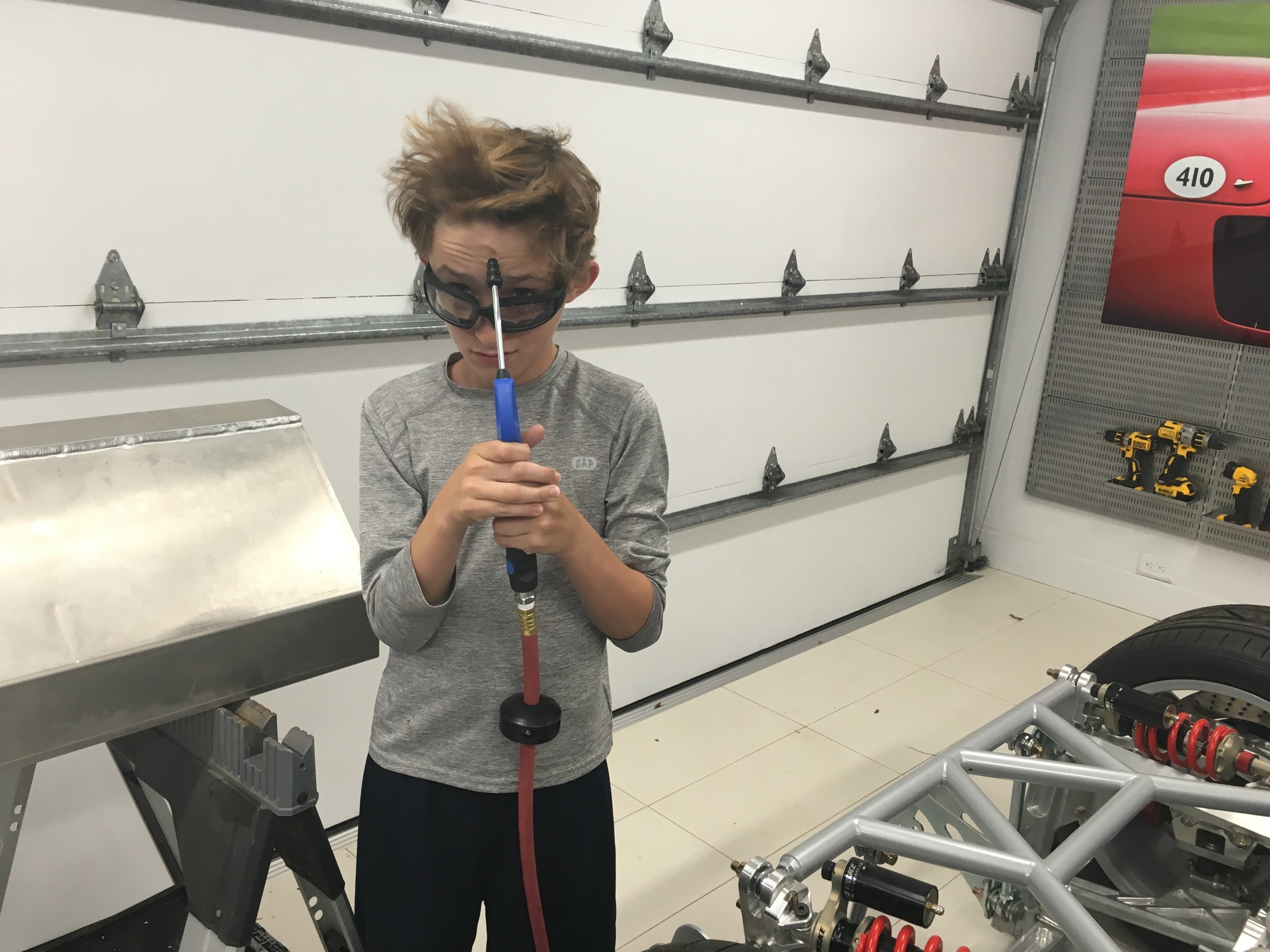
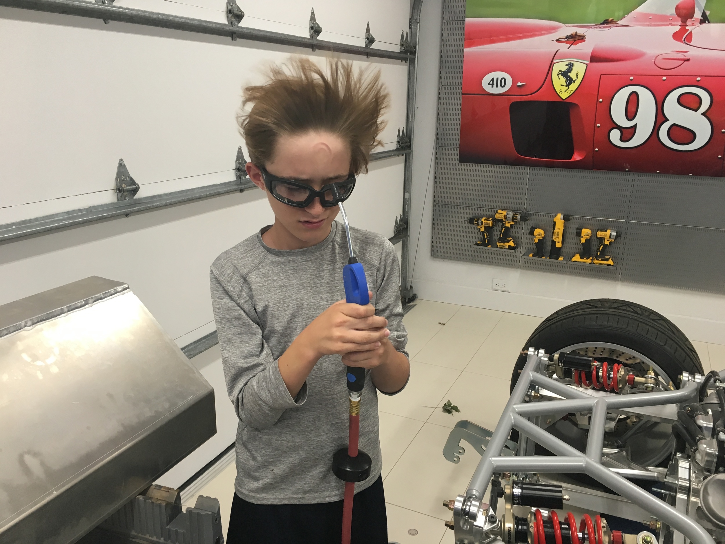
The best way to good results without winding up in the dog house is to use a vacuum forming machine. It's not too hard to build one, but I don't need another project. I had been eyeing one from Centroform, but I didn't want to spend $1,495 on an experiment. After spending some time searching eBay, Craig's List, etc., I found one in a local online equipment auction... and I won it for $193!

It has a built in 1,500 watt heater and two vacuum ports. One is for a shop vac and the other for a vacuum pump. A shop vac will remove a lot of air quickly, but it doesn't have the torque to create a strong vacuum to pull the plastic tightly against the mold. A vacuum pump moves less air, but it has the torque to create a strong vacuum. To put this in perspective here are some typical vacuum inHg (that's inches of mercury) for typical vacuum sources:

  • Single-stage vacuum cleaner: 3.7-4.0
  • Two-stage vacuum cleaner: 5.8-6.6
  • Mouth suction: 15
  • Vacuum pump: 27+

So the manly 5HP super vac moves a lot of air, but can only create a fraction of the vacuum of a diminutive vacuum pump. The Centraform machine has a pressure sensitive valve that automatically closes when the shop vac is no longer able to suction thus enabling the vacuum pump to evacuate what's left.

You might be wondering if the vacuum helps... well it does. If you were at sea level and could weigh a column of air that was one inch square, you would get something in the neighborhood of 14.7 pounds assuming you didn't have a high or low pressure weather system above you at the time. This is called atmospheric pressure and since we're born into it, we take it for granted. However, if I could create a perfect vacuum inside the mold (which I can't), the atmosphere would apply 14.7 psi to the entire mold. So the vacuum essentially results in an evenly distributed, perfectly shaped clamp which is exactly what we want when were forming a hot piece of plastic over a mold.

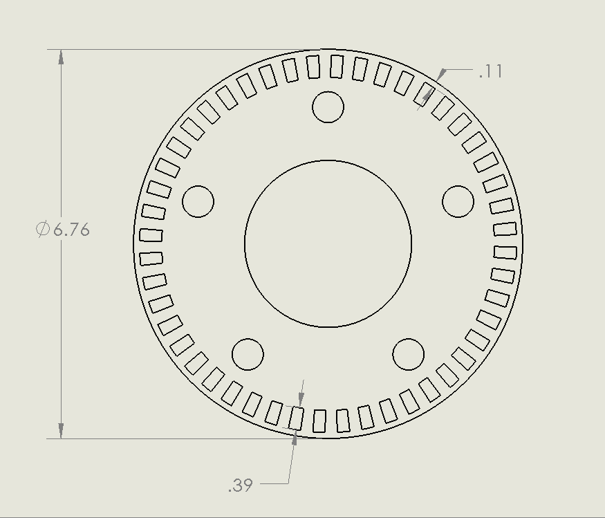
Male molds are simpler to work with when vacuum formingso one was 3D printed in ABS (that sounds right -- the male mold from Mars is simple whereas a female mold from Venus would require a myriad of strategically placed, and meticulously drilled vacuum holes to create the proper shape without marring the clear surface, an almost impossible task... but I digress). It was trivial to design because the profile of the bezel was already in CAD, so the profile was simply enlarged via an offset operation and then extruded to the desired depth. Since plastic shrinks as it cools during the part will adheres to the mold surface. To solve this the sides of the mold are tapered (referred to as mold draft). On a male mold, the minimum draft angle is 4 degrees. Fortunately SolidWorks has a draft feature built it.

Here's the specifics of first attempt:

Lens Material:

0.1" PETG (aka PET, PETE, PETG)

Mold:

  • Material: 3D print; red ABS with 6% infill
  • 0.1" offset
  • 0.1" chamfer on top edges
  • 0.1" chamfer on corner edges
  • 2.0" deep

I'm really happy with how well the shape and edges came out. However, every defect in the mold was perfectly transferred to lens. In particular you can see a pattern of triangular indents. We were in a hurry when we printed the mold so we set the slicer to a very sparse infill (it feels lighter than balsa wood) and we assume a combination of heat and pressure caused the triangular support structure to print through the top and sides. The mold was also very difficult to remove despite the 5-degree draft. We assume that the mold deformation was a contributing factor.

All in all a successful first test. With a few takeaways:

  • It does work as well as the YouTube videos (at least for 0.1" PETG)
  • Mold must be made stronger
  • Mold must be perfectly smooth
  • 0.1" chamfers worked well for 0.1" PETG

Next step is to buy some thicker PETG as well as research what other types of plastic might work well. I am also going to coat the mold with Evercoat polyester glazing putty, wet sand it and see how it holds up to vacuum forming.

First 3D Print of Tail Light Bezel

This is the first 3D print of the bezel that wraps the OEM bezel that I cut and filed down. The printer needs to be tweaked and we ran out of black filament, so the finish isn't great. However, it's good for the first attempt.

Some observations:

  • The triangular recess in the bottom right was added to provide a rectangular shape with a flat bottom. It will be filled with a piece of red reflector cut via laser.
  • The bottom middle is a little too wide. I'm thinking about thinning the top of the reflector triangle and perhaps creating a recess beyond the tip of the reflector.
  • I haven’t found the courage yet to cut the curve out of the left side of the OEM bezel yet, but that needs to happen. When that's done  the bottom left of the printed bezel will be vertical/straight with no curve. Before I do that, I want to be pretty sure that a 3D-printed bezel will likely work.

First 3D Print and Bezel

I need to design some parts to be 3D printed or CNC machined. I have no CAD skills and although I bought a 3D printer, a MakerBot 2x, a couple of years ago, I never fired it up. So it makes sense to do something simple first...

The removable side-impact bars utilize interlocking couplers. When they're removed the exposed couplers don't look good, so I'm going to make an end cap. I spent an entire day designing the part below. That includes sorting out the printer, installing and learning the CAD software basics and printing the part out. While one day seems like a long time for a simple part like the one the right, it would have been much longer without YouTube! Now that I know the dimensions of the part and the basics I can redraw the part in a few minutes.

I chose Autodesk 123D because it's free, it's approachable by beginners and it has pretty good reviews. In terms of researching packages I found this decision graph and this summary list very useful.

After designing the part, I decided that I wanted to go back and change the fillet on an edge... well the only way to do that is by clicking undo until you get to that step (assuming that the steps are still in the buffer) and then manually redoing all of the subsequent steps. The reason for this is that it's using a 'direct modeling' approach. When you make a change to a solid, such as cutting off a piece or applying a fillet, it's gone. There is no way to get it back other than undo. Parametric-based CAD stores all of the steps and you can go back to any step, change it, and then have that change automatically rippled forward. These packages are usually more expensive and more complicated to use, but that's the direction I'm going. I'm thinking about SolidWorks which is both expensive and overkill for what I'm doing.

I did a test print using the 3D slicer that came with the MakerBot. I would show you a picture of it but my wife threw it out thinking it was some 'Lego junk' -- apparently my kids shouldn't leave their Lego stuff anywhere near the kitchen. In any event, I wasn't crazy about the quality of the print so I bought and installed Simplify3D, a pro-level slicer (please don't tell Esmeralda that because I'd like to bank that mistake -- I'll need it for something I'm sure). However, I couldn't get it to communicate to the printer via USB and the SD card on the printer wasn't working. Frustrated, I searched for a local 3D print shop. I found 3D Hubs which enables you to upload a design and get instantaneous printing quotes from nearby shops. I picked Charles River Maker which is all of 3.4 miles away and had my part printed (they use Simplify3D as well). In the picture below you can see the white, 3D-printed part on the top coupler compared to the bottom coupler which doesn't have the part.

Jeremy was very helpful and he has a bunch of 3D printers (one large enough to print at least a prototype of my tail light bezel) as well as a laser cutter and other cool equipment.

Bezel

I spent several more hours cutting and filing the bezels and almost all of the extraneous pieces have been removed. The picture below is a scan of the passenger side bezel.

There are three primary issues that I'd like to deal with:

  • The right side of the bezel is on a 45-degree angle which hides part of the light and will look weird on a flat-tail car like the SL-C.
  • The right side of the bezel is curved on the top and bottom. The curve on the top should look good because the tail already has a similar curve there, but the bottom curve would look much better if it were straight.
  • The left side of the light is an inch and half or so shorter than the right side. It would look much better if they were the same height (i.e., the top and bottom were parallel).

I think that I can solve all of this by cutting the right side of the bezel off and 3D printing a bezel that surrounds the entire outside edge of the existing bezel (reproducing the interior bezel would be a massive amount of work) and extending the exiting bezel it in the desired places. 

I'm not sure how to import an image into a CAD package yet, so I just did the above in a paint program. It outlines the general direction that I'm thinking:

  • Blue Lines: ~7mm thick border
  • Red Line:  ~3.5mm thick border
  • Green Line: sits on lens and slopes back at what looks 45 degrees per existing piece
  • Yellow Triangle: fill between the blue lines at top surface
  • Orange Triangle: 8mm recess to glue custom-cut reflector on

Tail Lights

I don't like the round tail lights that come with the kit. I really like the newer Lamborghini lights, but they're $4.6k a pair. Which, of course, is just the starting point; before you get into electrical, body work, custom bezels and any mistakes. After looking at countless images online and looking at every car on the road, I decided on aftermarket lights from Buddy Club that were designed for a Toyota FT86, Scion FRS, and Subaru BRZ. They have Lambo-like sequential LEDs, they are relatively flat (a big requirement for the SL-C) and most importantly they are Department of Transportation (DOT) certified. This video shows you what they look like in action.

So I ordered a pair. They look well made, but I sure as hell wish they didn't have "Buddy Club" on the clear lens. I should be able to carefully file and polish that out right? Well no, the letters are on the inside of the lens.

Using a 12v power supply, Will and I were able to quickly determine the basic wiring:

Black: Ground
Black with White Stripe: Brake
Red: Running
White: Turn

The back has four M4 mounting bolts.

In the picture below paper templates have been taped on to show the rear vents, the license plate and the general outline of the "Lambo" tail lights.

The curved bottom section doesn't go with the shape of the tail and it will need to be removed. Fortunately that section is just a non-functional reflector. It looks like the lights could be made to work, but it's going to take a lot of body work, custom brackets, custom flanges, custom clear covers and modifications to the light's housing. Fortunately no changes will made to the LEDs themselves.

So, decision point. Do I a cut up a $550 set of lights and put a hole in the tail section? Hell YES these things are cool!

The clear plastic lens has been cut off with a Dremel abrasive cutoff wheel... made a real mess.

The three screws that hold the rear cover have been removed, the flash mode switch has been cut out and several flanges have been removed. With respect to the switch, open circuit is flutter mode and closed circuit is normal blink mode.

Four screws have been removed to separate the bezel from the LED panel and electronics.

The passive reflector has been removed and the housing was trimmed so that the bottom curved portion can be hidden behind the fiberglass body.

It was really worried about how I was going to blend the light into the tail because the clear lens sloped about 1" from left to right which wasn't going to look right for a flat tail. Other than a 1/4" raised portion of the bezel, which could be ground down, patched and painted, the bezel is flat. Of course I now need to figure out how to make a lens!

The Engine's Where?

You don't have to be a mechanic to realize that something's not right with this picture. The pipe coming out of the engine that is within a 1/4" of an inch of t-boning the chassis is the outlet for the water pump. It's a LS7-based engine and like most engines it expects to be in the front of the car with the radiator directly in front of it. In the case of a mid-engine car, the driver sits between the engine and radiator.

There isn't much room and many builders just notch the pipe and weld it into a into a sharp 90-degree angle. Beyond not looking nice, this approach can lead to cooling problems because there will no doubt be turbulence and turbulence creates air bubbles. Consider that 2% air in the system results in 8% less heat transfer, but 4% air results in a whopping 38% less! 

Fortunately the existing tube is press fitted into the water pump and not hard to remove. After much research I just did what my friend Will did. I had John at Design Enterprises build me a custom part. He machined one end of a stainless steel 90-degree elbow so that it can be press fitted into the water pump. He then machined an adapter from a solid block of stainless steel and TIG welded it to the other end. The adapter serves two purposes: it provides a pronounced bead so that the silicone coolant tube won't slip off and it smoothly transitions from the pump's 1.25" diameter to stainless cooling tube's 1.5" diameter.

This is what the part looked like when I recieved it. 

Some of the weld created a ridge on the inside edge which I filed smooth to reduce turbulence. I also decided to sand the raw tube with 220 and a refinishing pad to give a satin patina and use polishing compound to remove the heat marks from weld. This is what it looks like now. It's ready to install, but I'll have to pull the engine to do that.

To put even a simple thing like this in perspective, I spent a little time here and there over a couple of months thinking about what I might do. I then ordered the part which took about a month to get at which point I spent several hours cleaning it up... and it's still not installed yet!

Pedals

72-603_front_wide1-500x500.jpg

The kit came with a beautiful set of Tilton 72-603 pedals. As you'd expect from a premium racing pedal assembly they are well engineered and massively configurable. The latter being a bit of an issue as the instructions merely state that "pedal position is highly dependent on the driver's preference" and you're looking at bunch of parts on the bench.

The first step is to mount the pedals. The brake pedal is wider than the gas and clutch pedals -- makes sense as the most important thing in any car is stopping. Each pedal can be installed in one of two orientations that provide different mechanical ratios. I wasn't sure which I would prefer so I just picked one. In addition each pedal can be installed in one of two bolt positions which will change the height by 1/2". Since I have small feet, I chose the shorter option -- don't go there, small feet means small shoes and that the body can expend resources growing other appendages. In any event all of these settings will be easy to change even when the pedals are mounted in the car.

The next step was to determine how the pedals should be positioned. With a 1,000 HP motor in a very light car you want the throttle pedal throw to be as long as possible, so I adjusted the min and max limits accordingly.

Next I installed the clutch, front brake and rear brake master cylinders. I upgraded the Wilwood master cylinders to Tiltons because I believe the Tiltons are superior and they use a -4 AN fitting for the reservoir feed rather that a rubber hose and barb, and they have an additional -3 AN fitting on the pressure side which will allow me to cleanly install pressure sensors. Interestingly the front break master cylinder is ¾” and the rear is 7/8". Why? Well during braking a car's momentum shifts forward so more braking is done by the front brakes. So shouldn't the front master cylinder be bigger? Nope, for the same amount of pedal travel the smaller cylinder will generate more pressure.

Next I ensured that the front/back brake bias balance bar was set to 50/50 which means that I actually have front bias because the front cylinder is smaller. Note that I will add a an adjustment knob so that I can change the bias while the car is in  motion. I then positioned the brake pedal so that it was closer to the driver than the throttle to facilitate heal-and-toe shifting. I think it's right, but I won't know for sure until I drive the car. To achieve this I had to cut the threaded shaft on both the front and rear brake master cylinders. As can be seen in the picture to the right, the Jet belt sander does a great job at cleaning up the cuts.

Throttle Linkage & Throttle Position Sensor

Since the car is drive by wire (DBW) I purchased Titlton's throttle linkage kit. Like everything Tilton, it's very well made. However, I had an issue with the lock nut on the max travel stud hitting the bracket. I checked things out multiple times and figured that I could grind the bracket, but that didn't seem right for Tilton quality so I called their tech support and sent them some pictures. They called me back about an hour later. Apparently the holes in the bottom of the bracket are asymmetrical and the shaft had been installed backwards at the factory, thus moving the bracket slightly towards the throttle pedal. The picture on the left shows the asymmetrical bottom and the picture on the right shows the symmetrical top. After taking it apart and reassembling it everything was fine.

The bracket is designed for a Penny & Giles TPS280DP sensor. Apparently it’s a very nice hall effect sensor, tested to 60 million operations, 12-bit resolution, zero signal degradation over the lifetime of the sensor, sealed to withstand high pressure wash-downs (IP69K), dual outputs, etc.

All wonderful, but after spending hours of googling around I found all types of press releases, specs, etc., but no place to buy it online. After sending a bunch of emails to the manufacturer and re-sellers I received one quote: $250.04 and “approximately 6-8 weeks” delivery --  two months, really?

When I asked about the lead time for a replacement in case of failure, they suggested that I buy two! Clearly they forgot to mention that parts of it were made of unobtainium. After posting in the GT40s forum one of the members to me that Jenvey Dynamics white labeled as part number TP8LH. The LH indicates that the throttle value increases in the anti-clock-wise direction which is British for counter-clock-wise. In any event, I found an online retailer in the USA which offered it for $90 less.

Reservoir Connections

The reservoir connections were plumbed with -4 AN couplers and crush washers. The hose and fittings will be done at a later time.

Pressure Sensors

I replaced the supplied brake pressure switch with three high-end pressure transducers on the font brake, rear brake and clutch master cylinders. This will enable me to log the values and have the MoTec Power Distribution Unit (PDU) take actions based on the pressure. The connection required a special -3 AN Male to 1/8" NPT Female connector into the extra -3 AN port on top of the cylinders. The pressure sensor required a 1 1/16" wrench to tighten, which is the first time that I've used that wrench. Ironic that the tiny pressure sensor required a wrench much larger than all of the manly suspension pieces.

All of this resulted in a very clean installation.

New Friends

I've met a lot of great people chasing the SL-C dream and two of them, Will and Peter, stayed over for a couple of days to help out with the car. We discussed many things, found issues with parts and discovered some big challenges to think through. For example, the supercharger intake tube interferes with the gas fill tube (car kinda needs gas), the condenser was damaged during shipping, the evaporator won't fit due to the custom track-day bars, the banjo couplings on the brake calipers needs to be machined to fit BremboGTs which are much larger than the stock brakes, etc. Even these set backs represent progress because you can't solve them until you find them!

On the one step forward side, we cut an opening in the tail for the rear window. While the window hasn't been fitted yet, you can in the second picture that the carbon fiber vents have been fitted (but not installed). They are beautiful pieces and help mitigate one of the largest challenges with a mid-engine car -- keeping the engine cool. Cinder inspected them and she certainly thinks they're cool!

We were also able to get the majority of hard brakes lines and clutch line mounted to the chassis with some nice red clips from Made 4 U Products. The passenger-side rear brake line needs to be cut and flared for a better fit and the line running behind the fuel tank will need more clips installed, but that will have to wait until the engine is pulled.

Fuel Tank Mounted

It's important to isolate the fuel tank from the chassis to reduce stress and vibration that can lead to cracks or other failures. It's also critical that it stays put in the event of an impact or a roll over. It stores and 19.2 gallons which equates to about 116 pounds which, when multiplied by whatever Δv (hopefully small), means that you want to ensure that it's well mounted.

The tank is positioned as far as possible to the passenger side to provide better weight distribution when there is no passenger (I'm also a little heavier than my wife!)

I was going to fabricate brackets from 90° angle aluminum, but I found some nice ones from 80/20 Inc. They are clear annodized and gusseted for extra strength.

The self-adhesive rubber was cut to size and applied to the chassis and brackets. Two small brackets were installed to support the lower rear of the tank. Since they partially sit on welds, the bottoms needed to be machined for them to sit flat. Two large brackets were mounted on top of the tank and one large bracket was installed on the side of the tank to keep the tank from sliding to the driver's side (the passenger's side of the tank is stopped by the chassis).

I think that I'm going to install one more large bracket on the large cross member to prevent the top of the tank from tilting backwards, but I'll need to pull the engine to gain access.

Man Card Revoked?

Over vacation, whenever I was taking too long to get in the chilly ocean water, my daughter would threaten to revoke my man card. Today that got me to pondering,

"If I get as excited about garage cabinets as my wife does about kitchen cabinets, is my man card going to be revoked?"

I'm sure you're wondering what the catalyst was for this 'deep' introspection.. it was Joe from Motorhead Extraordinaire who installed a new set of Lista cabinets. They support 440 pounds per drawer and are what the aerospace guys use, so I did an appropriate number of Tool Man Tim grunts... and, yeah the man card is safe for today LOL.

The bench height resulted in the drill press being too tall (top right picture), so I cut the pole by a little over 8". I also had to modify the the table rack to fit in the reduced space. The 14" Metal Devil blade cut them both like butter... look how smooth the cut was in the bottom left picture (that's without any filing). I only needed to do minor deburring and beveling. Nothing like having the right tools.

Bubbles

Having cleaned the fuel tank and installed the fuel-level sender, the next step was to pressure test it. The tank has as a lot of TIG welding and if there’s a leak you want to find it before you install it and fill it with gas. I temporarily plumbed a Schrader value into the top left NPT port, a pressure gauge to into the top right NPT port and a  ½” NPT to -10 AN fitting with a cap in the bottom port. I pressurized the tank to 5 psi and went to dinner. When I returned the tank was down to 3 psi – I had a slow leak.

To find the leak, I mixed dish soap with a little water and brushed it on all of the seams. Fortunately, none of the tank seams leaked, but all of the NPT ports were leaking. I was surprised and how many bubbles a slow leak produced. I tightened the brass fittings as much as I dared, but they still leaked. While NPT threads are tapered, they don’t have a flare like you’d find in an AN fitting and they are often sealed with Teflon tape. However, Teflon tape isn’t compatible with fuel and if you’re not careful a piece might wind up in a fuel injector. Instead, I bought some Permatex Aviation Form-A-Gasket, applied it to the treads and no leaks! Next step is to install the tank.

Good Project for Hot Day

It was hot and humid which presented a good opportunity to remove all metal chips and dust from the fuel tank. The NPT openings were sealed with brass plugs and the fuel filler opening was sealed with this rubber end cap from Home Depot. The tank was filled with water via fuel-level sender opening and Connor was recruited help spill it out of the tank. The first rinse didn't result in any debris that I could see, but my OCD required that do it three times. Connor was having fun and he demanded that we do it a fourth time, so it's one clean tank.

When then tank was dry, I poured several cups of acetone into the tank and sloshed it around on all sides to remove any residue. 

The fuel-level sender provided in the kit is very nice. It is customized to take the unique shape of the tank into account and it measures capacitance so it has no  moving parts. The sender was mounted with five 10-24 bolts, #10 washers and the supplied cork gasket. Loctite 442 (aka blue Loctite), which is compatible with fuel, was applied to the threads.