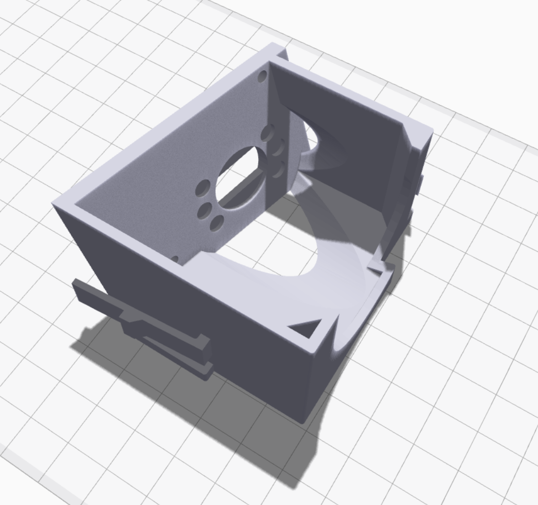
I wanted to fit the dashboard so that I could check how much space I could gain for the evaporator when I cut a hole in the monocoque. The first step was to trim the ends to clear the front roll hoop. The dash has molded lines so this was a simple task. The Snap-on reciprocating tool was used to cut the corners and the the jig saw was used everywhere else because it's easier to maintain a straight line.
Stalk on the left and new switch on the right
I then dropped the dashboard in. Holy crap... despite the car being wide, the cockpit is extremely cramped... just like a race car should be. The right stalk on the on the steering column projects in front of the middle binnacle where the controls and/or a tablet will go. In addition, the stalk has a large number of windshield wiper settings and the wiper motor only has two speeds. The solution is to replace it with a smaller 80173 switch from Painless Performance.
The stalk was very easy to remove once I figured out how it was done. There are two recessed tabs, one the top and one on the bottom. You simply depress the top one with a a flat screw driver and the bottom one with your finger and pull. Separating it from the wiring harness was also easy; cut one wire tie and pop off one reusable wire clamp.
The next challenge was figuring out how to mount the switch. My first attempt was to 3D print two round pieces that sandwiched the switch around the steering column's upper and lower plastic covers. While it was easy to make the parts, it's a pain in the ass to install the switch and I will have the covers on and off a bunch of times during the build.
There's a reason the OEM version is mounted to the steering column, so that's what I decided to do. In the end it was a lot more difficult than I first thought - first time that's happened on this project LOL. The most challenging parts were the two clips (I'd like to thank GM for making them different shapes) and figuring out the exact position switch which requires a compound plane. I printed it in two pieces; the main box and a cover which completely hides the shaft and nuts.
The following pictures show the assembled module. I thought about designing clips to hold the cover in place, but after the first two clips I am done with clips for a while and the screws and nylocs work just as well.
As can be seen above, the switch protrudes through the side of 3D box. This requires a little material to be removed from the plastic receiver on the steering column. This is easily achieved with a sanding drum on a Dremel. The spade connectors also need to be cut shorter to fit. The plan is to solder a wire to them and crimp a connector on the other end. This is exactly what the OEM version does.
The following video shows how easy it is to install and remove the module. Listen carefully for the click... that has to be the most gratifying click in my entire life ;-)
In the picture below I'm holding the top and bottom steering column covers in place. The switch doesn't look like it's centered in the hole, but that's just an optical illusion.
Switch with the upper and lower steering column covers held in place
The switch is actually two switches; a three-position rotary switch (off, low, and high) for wiper speed and a momentary switch for fluid. The provided Infinitybox harness only supports one speed, but the wiper motor has two speeds. Since I'm going with a MoTeC PDM and a custom harness, I will have two speeds. In addition, I will use the fluid button to toggle an intermittent wiper function. Since the motor is self parking a one-second pulse with a configurable wait interval should provide OEM-like intermittent functionality. Holding the button down for more than one second will set the interval for the amount of time that the button is depressed.
I learned a lot, including a couple of basic tips when modeling things in 3D:
First, when you want to maintain a dimension make sure that you specify it from a point that doesn't change. For example, consider the simple box shown below. The first step is to draw and extrude the bottom. You draw the sides (likely using the offset command) and extrude the walls. Very simple. However, I typically draw on the top plane of the bottom piece because I'm extruding up -- seems intuitive to me. To do this, you simply subtract the height of the bottom from the desired height. However, if you later change the height of the bottom, you also change change the overall height. Sometimes, that's what you want, sometimes not. If you want to maintain the overall height, you draw on the bottom plane of the bottom piece and extrude to the desired total height. I found it a little counter intuitive to extrude the sides through the bottom piece, but it works just as well, no math is required and changing the height of the bottom has no effect on the overall height.
In the pictures below the bottom is 0.2" tall and the overall height is 0.7"
Second, I found that I had issues getting the edges defined by the intersection of planes at weird angles to look clean. The fix is to extrude one or more of the pieces well over the desired edge and then to simply extrude cut what's hanging over the edge. This is conceptually similar to how laminates or veneers are fitted in the real world. The pieces are cut larger than needed, glued into place and then trimmed with a router.


