America first; stop sending all of those cars
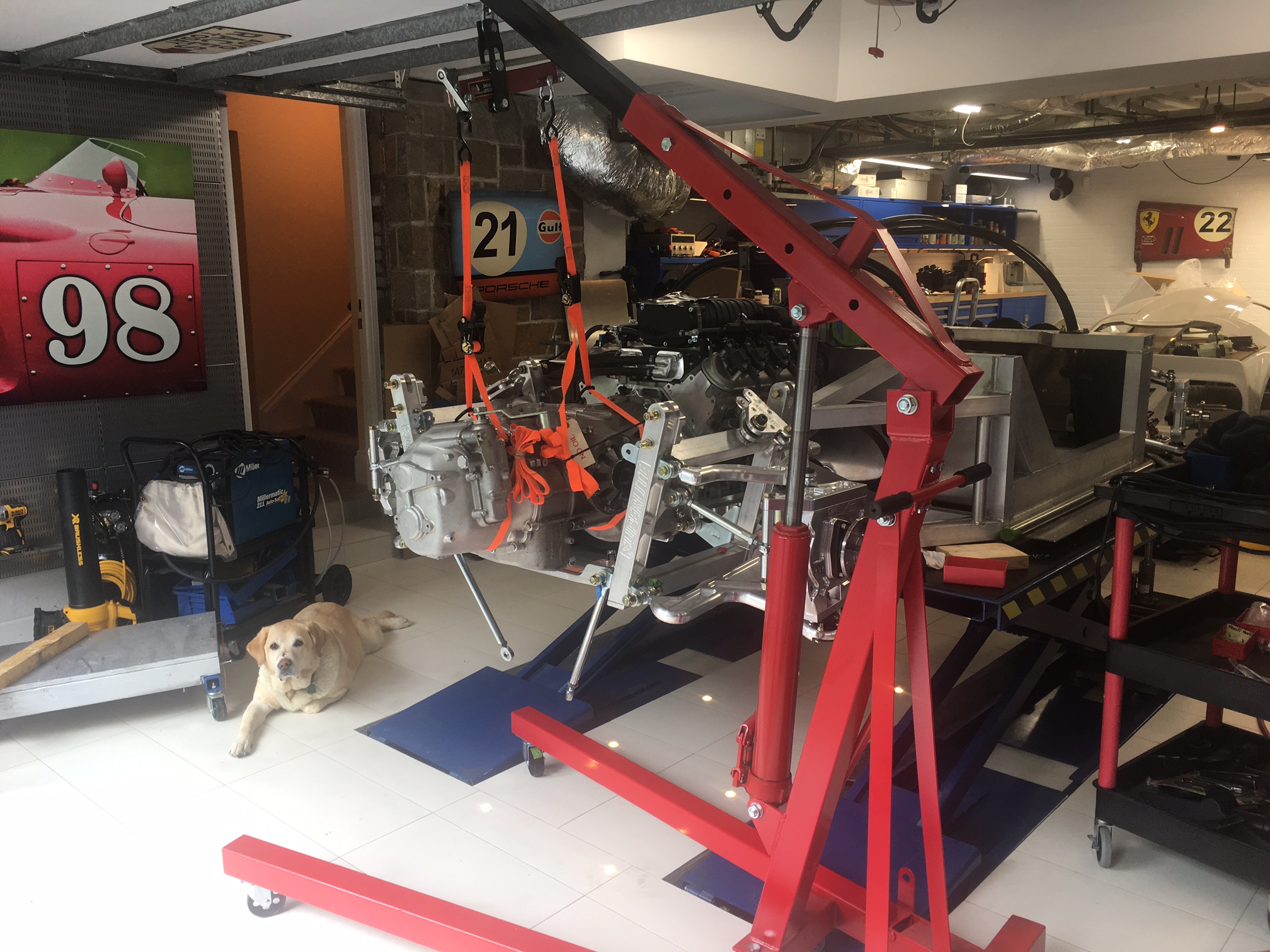
I installed the transaxle for fitment purposes today (i.e., without the flywheel, clutch and pressure plate). Holy crap is that thing a monster... let me express it in Trump speak because, apparently, that entitles you to say whatever you want.
"It's huuuuge... much bigger than the Porsche or Graziano transaxles. It's designed for an America-first V8 and supports the most ever horsepower... not like those weak, whinny-sounding, Euro-trash engines." Of course CNN would have to explain that the Ricardo is actually made in the UK and that some people actually like the sound of those engines built by our allies.
Engine hoist load leveler
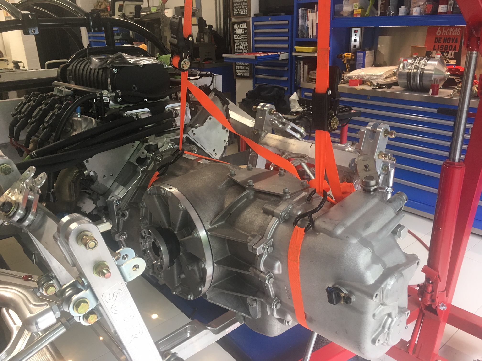
The first step was to remove the shocks and rear suspension cross brace and to find someone to help me. We used two ratchet straps to connect the transaxle to an engine hoist load leveler. Rotating the full-length screw tilts the leveler which is very useful when trying to compensate for off-center loads or adjusting the load to a certain angle. While the leveler made it easy to adjust the transaxle lengthwise, we had to adjust the straps a couple of times to get everything level left to right.
Six M10-1.5 hex head screws mount through the transaxle adapter plate which has hex-shaped recesses that keep the screws from spinning. The top four are sandwiched between the engine block and the adapter plate so they act like wiggly studs. The bottom two screws are easily removed. After multiple attempts to line everything, we realized that two of the screws had a slight bend. So we threaded several nuts on each to protect the threads and wacked them a couple times with a hammer -- problem solved. We were then able to get one of the locating pins (installed in a previous post) in without too much effort, but the second one refused to go it. We put a little anti-seize on it and after an appropriate amount of profanity we got things lined up. It was a lot more difficult than I expected to pull things together which I assume that was due to the tight fit of the locating pins.
The only way to pull everything together is to tighten the six screws, but because of their length we had a hard time getting the nuts started. In fact, on the bottom we had to temporarily use longer screws. We then very carefully tightened everything down in a star pattern to rock it down so as to not crack the cast aluminum bell housing. I'm now wondering how the hell I'm going to get it off and if I should take the adapter plate off and use longer screws.
I forgot to mention that we got it half way on once and then realized that the washers and nuts that are used to mount the adapter plate to the chassis bracket were in the way (see picture below). Everything off and then on again. Practice makes perfect, right? The cool thing about my 3D printer being cloud based is that even though I'm traveling I was able to design a simple custom spacer and kick of test print. It will be waiting for me when I get home and if it fits, I'll have it machined out of aluminum.


